Note! The solar modules connected to the inverter must comply with the IEC
61730 Class A standard.
Note! When photovoltaic modules are exposed to light, they supply current to
the inverter.
General com-
ments regarding
PV modules
To enable suitable PV modules to be chosen and to use the inverter as efficiently
as possible, it is important to bear the following points in mind:
-
If insolation is constant and the temperature is falling, the open-circuit
voltage of the PV modules will increase. The open-circuit voltage must not
exceed the maximum permissible system voltage. If the open-circuit voltage
exceeds the specified values, the inverter will be destroyed and all warranty
claims will be forfeited.
-
The temperature coefficients on the data sheet of the PV modules must be
observed.
-
Exact values for sizing the solar modules can be obtained using suitable cal-
culation tools, such as the Fronius Solar.creator (creator.fronius.com).
IMPORTANT! Before connecting up the solar modules, check that the voltage
for the solar modules specified by the manufacturer corresponds to the actual
measured voltage.
DC terminals
DC-
*
DC =
DC1+ DC2+
*
min. 2,5 mm² - 16 mm²
DC Con Kit 25
6 - 25 mm²
DC Con Kit 35
> 16 - 35 mm²
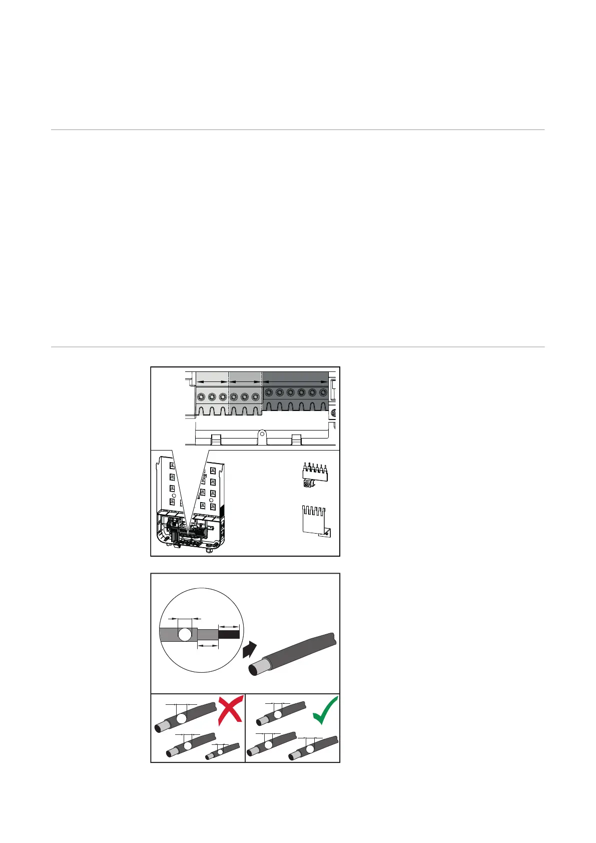
Max. cross-section of each DC cable:
16 mm²
Min. cross-section of each DC cable:
2.5 mm²
The DC cables can be connected to
the DC terminals without ferrules.
IMPORTANT! When using ferrules for
DC cables with a cross-section of 16
mm², the ferrules must be crimped
with a right-angled cross-section.
The use of ferrules with insulating col-
lars is only permitted up to a max.
cable cross-section of 10 mm².
D1
D2
D3
D1
D1
D1
15 mm
70 mm
D > 6 mm
min. 70 °C / 167 °F
For double insulated DC connection
leads with a cable diameter greater
than 6 mm, 70 mm of the outer jacket
must be stripped in order to connect
the cable to the DC terminal.
IMPORTANT! To ensure effective
strain relief of the solar module
strings, only use cables with identical
cross-sections.
28
 Loading...