6
Warning! Operating the equipment incorrectly can cause serious injury or
damage.Do not use the functions decribed here until you have read and comple-
tely understood all of the following documents:
- these Operating Instructions
- all „Operating Instructions“ for the system components, especially the
„Safety rules“
Note! Owing to software updates, you may find that your machine has certain
functions that are not described in thesese Operating Instructions, or vice-versa.
Also, certain illustrations may be very slightly different from the actual controls
on your machine. However, these controls function in exactly the same way.
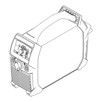
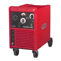
Fig.5 Front view and rear view of TP 1500
(1) Mains switch
(2) Shielding-gas connection socket (TP 1500 TIG only) ... for connecting the gas
hose
- when using an TTG 1600 A welding torch
(3) Dust filter ... in the air-intake zone of the fan
- prevents the inside of the housing from getting soiled in heavily dust-laden
environments
Note! We recommend always using a dust filter in the power source.
(4) - Current socket with bayonet latch ... for connecting:
- rod-electrode or earthing cable for rod-electrode welding (depending on type of
electrode)
- earthing cable for TIG-welding
(5) - Current socket with bayonet latch ... for connecting:
- rod-electrode or earthing cable for rod-electrode welding (depending on type of
electrode)
- welding torch for TIG welding (current connection)
Safety
Power source
(4)
(5)
(1)
(2)
(3)
Controls and connections
 Loading...