ASSEMBLY
OM 0408SB1184-A
24
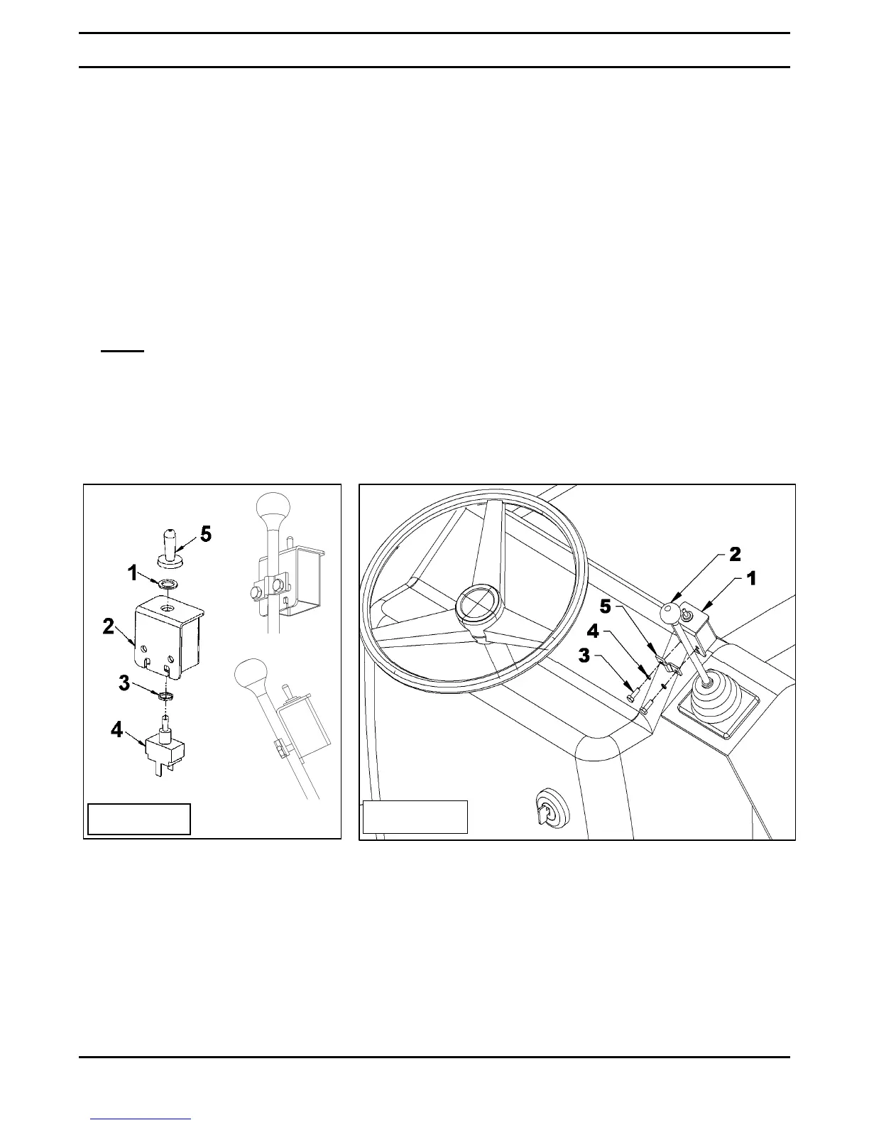
7. Figure 18: Insert the switch (item 4) in the
switchbox (item 2), secure with the two nuts
(items 1-3) provided with the switch, and
screw the rubber cap (item 5) in the order
shown on figure.
8. Figure 19: Place the switchbox (item 1) on
the lever so to get a comfortable working
position when the hand is on the knob and
secure with the switchbox clamp (item 5),
using two 1/4"NC x 3/4" bolts and two 1/4"
lockwashers (items 3-4) by placing the
clamp so to not block the switchbox lower
openings.
NOTE
: Tighten bolts just enough to attach
the switchbox to the lever solidly. DO NOT
TIGHTEN TOO MUCH to avoid deforming
the clamp.
9. Figure 16: Connect the ring terminal of the
ground wire (item 1) to a ground screw of the
vehicle.
10. Figure 16: Connect the fuse wire (item 3) to
the tractor switch wire using a tap connector
(item 5).
11. Figure 16: Connect the actuator double wire
(item 4) to the actuator (item 7).
12. Figure 16: Cover all wires with the loom
(item 6) and attach with tie wrap.
Figure 18
Figure 19