ASSEMBLY
OM 0408SB1184-A
20
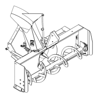
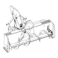
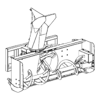
Installation of Snowblower with Quick Hitch
(Figures 12-13)
SB1184
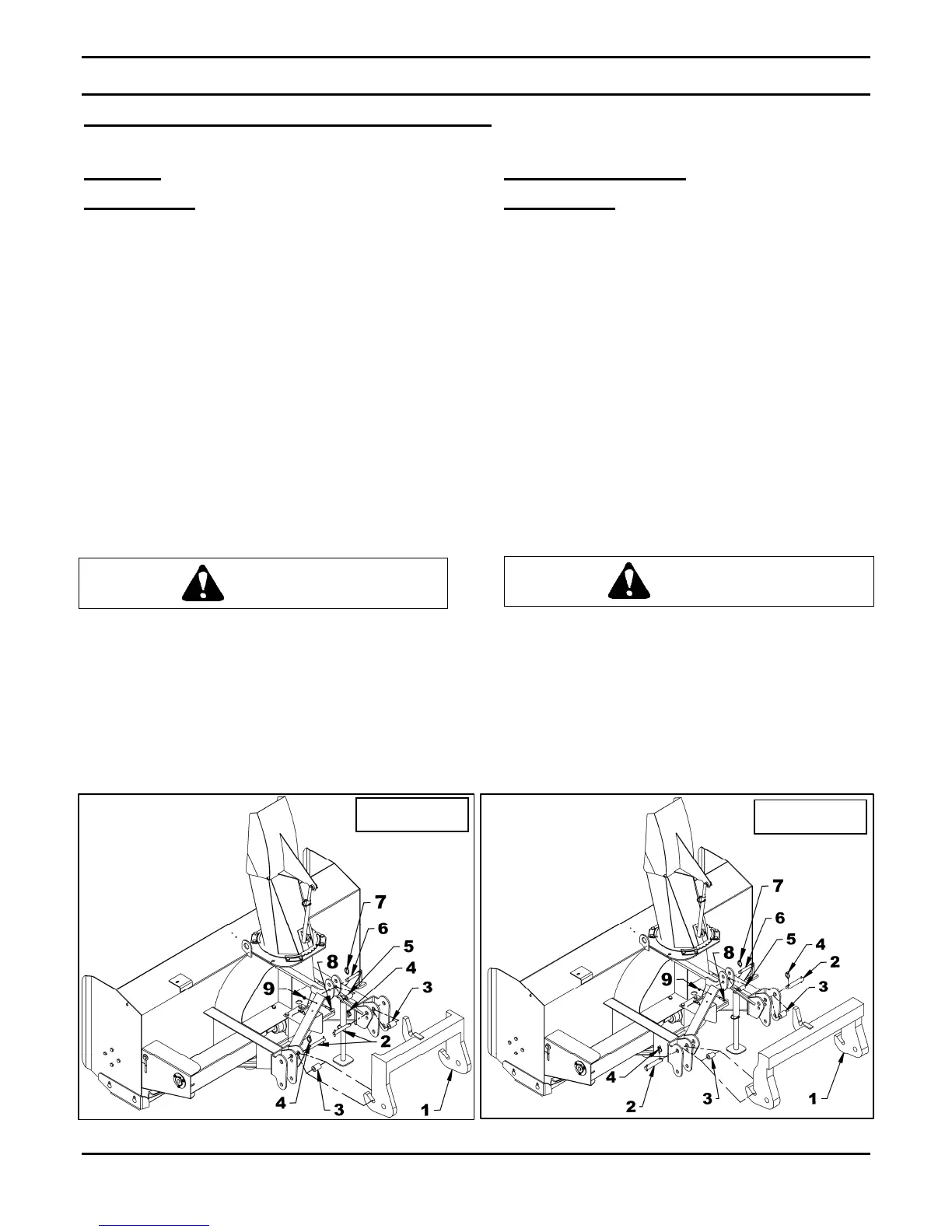
CATEGORY 1
(Figure 12)
1. Place the two 1 1/2" x 2 1/8" lg bushings
(item 3) between upper holes of the interior
and middle plates, insert the 1 1/8" x 6 1/4"
lg cat.2 pins (item 2) from the inside and
lock in place with 7/16" linchpins (items 4).
2. Insert the 1 7/8" lg bushing (item 5) between
the upper attaching plates and lock in place
with the 3/4" x 5 7/16" pin and a 7/16"
linchpin (items 6-7).
3. Install the eyebolt (item 8) in the upper hole
of the left or right side of the three point
hitch by screwing the eyebolt nut to the top
and locking eyebolt in place with a 3/8"
serrated flange nut (item 9).
Before connecting snowblower driveline to
tractor drive shaft, make sure driveline is not
too long in raised, lowered and middle
position. If the driveline is too long it must be
shortened, to avoid damaged to tractor. See
pages 24 to 26 for instructions.
SB1184 & SB1194
CATEGORY 2
(Figure 13)
1. Place the two 1 1/2" x 3 3/8" lg bushings
(item 3) between upper holes of the exterior
and middle plates, insert the 1 1/8" x 6 1/4"
lg cat.2 pins (item 2) from the outside and
lock in place with 7/16" linchpins (items 4).
2. Insert the 1 7/8" lg bushing (item 5) between
the upper attaching plates and lock in place
with the 3/4" x 5 7/16" pin and a 7/16"
linchpin (items 6-7).
3. Install the eyebolt (item 8) in the upper hole
of the left or right side of the three point
hitch by screwing the eyebolt nut to the top
and locking eyebolt in place with a 3/8"
serrated flange nut (item 9).
Before connecting snowblower driveline to
tractor drive shaft, make sure driveline is not
too long in raised, lowered and middle
position. If the driveline is too long it must be
shortened, to avoid damaged to tractor. See
pages 24 to 26 for instructions.
CAUTION
CAUTION
CATEGORY 2
Figure 13
Figure 12
CATEGORY 1