Page 9 of 18
INSTALLATION INSTRUCTIONS
© FS.COM 2016
FS016
For Technical Support: www.fs.com/service.html
2.2.3 Install the Switch on a Workbench
In many cases, users do not have a standard 19” rack, so people often place switches on a cleaning working platform. Such
operation is relatively simple, and the only following aspects should be concerned during operation.
Ensure the working platform is stable and well earthed.
A 10 cm space around switch is left for heat dissipation.
Do not place heavy objects on switches.
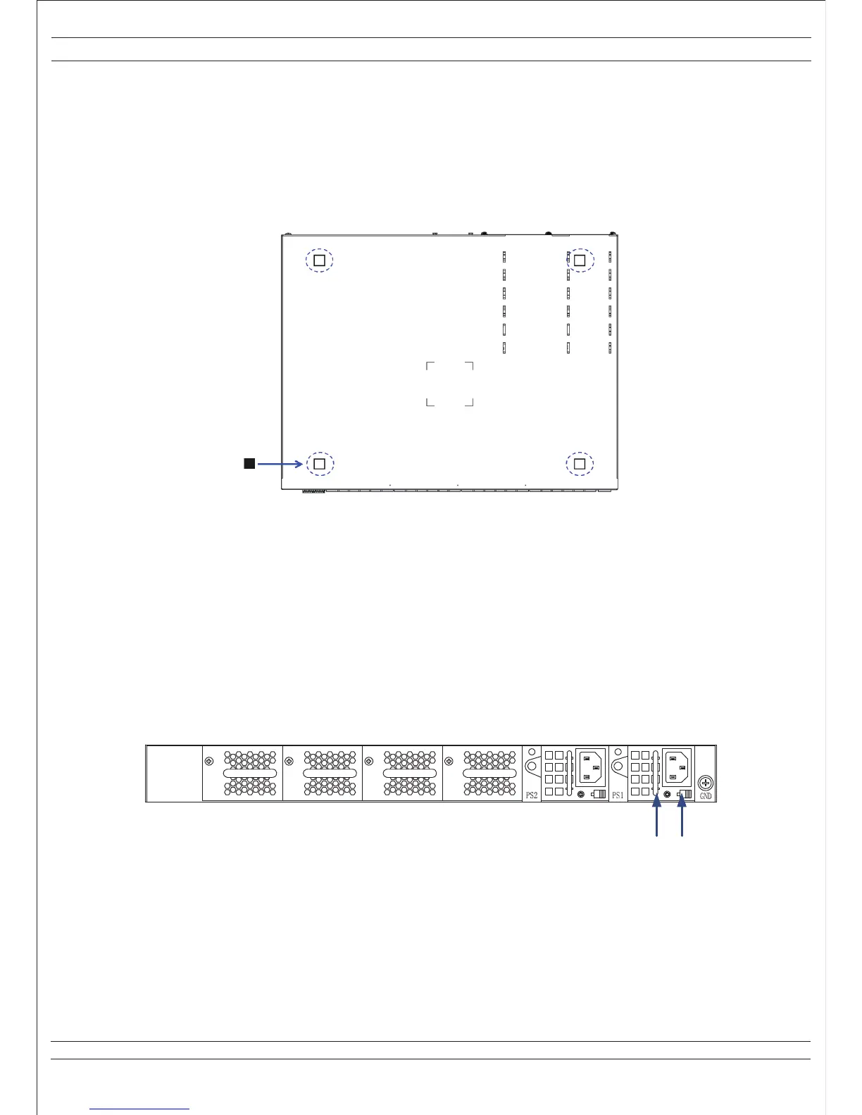
There are 4 foot pads that come with the device. Paste them onto the bottom near the corners of the switch, as shown below.
Figure 2-4 Installation Sketch Map of the Foot Pads
2.2.4 Installation and Removal of Power Module
Installation Process
The power module for FS S8050 series switch is pluggable. Installation process of power module is as follows:
• Wear ESD-preventive wrist strap, and confirm that the anti-static wrist strap is well earthed.
• Maintain correct up-down direction of power module (in line with the positive direction of characters, if turned upside down,
the power module cannot be inserted to the end due to structural limit specially designed inside chassis).
• Grip the handle on the front end of power module to be installed with one hand and support the bottom of power module
with another hand, and insert the power module by smoothly sliding along the power slot until the plug of power module
comes into full contact with the socket inside chassis.
• The locking switch of the power supply unit will lock the power module.
Figure 2-5 Installation Sketch Map of AC Power Module
Description:
(1) Handle of the Power Supply Unit
(2) Locking Switch of the Power Supply Unit
21
 Loading...