Page 2 of 18
INSTALLATION INSTRUCTIONS
© FS.COM 2016
FS016
For Technical Support: www.fs.com/service.html
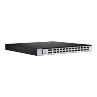
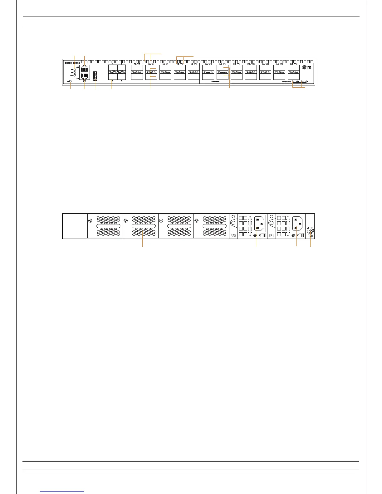
1: 10G SFP+ Ethernet Ports
2: 40G QSFP+ Ethernet Ports
3: 100G QSFP28 Ethernet Ports
4: 40G/100G Ethernet Ports Breakout Status LED
5: 40G/100G Ethernet Ports Status LED
6: ID LED (Locate the Switch)
7: Management Ethernet Interface (MGMT)
8: USB Interface
9: System Status LED (SYS)
10: RJ-45 Console Port (CON)
11: Airflow Input Holes (Front to back airflow)
1: Grounding Screw
2: AC or DC FRU Power Supply Module (PS1)
3: AC or DC FRU Power Supply Module (PS2)
4: Cooling Fans
1.2 Front Panel (S8050-20Q4C)
Figure 1-2 Front Panel Sketch Map of S8050-20Q4C
1.3 Rear Panel (S8050-20Q4C)
Figure 1-3 Rear Panel Sketch Map of S8050-20Q4C
6 7 8 1
9 10
2
4
3
5
11
4 3 2 1
 Loading...