List of Tables
Table 1-1 FS S8050 Series Switch Model ..……………………………………………………..…………………………………......
Table 2-1 Temperature/Humidity Requirements ………………………………………………..……………………………….…..
Table 2-2 Dust Content Requirements in Switch Room ……………………..…………………………………………………...
Table 2-3 Harmful Gas Threshold in the Equipment Room …………………………………..………………………….……...
Table 3-1 RJ-45 to DB-9 Cable Sequence ……………………………………………………..…………………………….………..
List of Figures
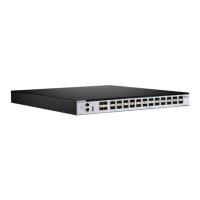
Figure 1-1 FS S8050 Series Switch ……………………………………………………..……………………………………………….....
Figure 1-2 Front Panel Sketch Map of S8050-20Q4C ……………………………………………………..…………………….….
Figure 1-3 Rear Panel Sketch Map of S8050-20Q4C ……………………………………………………..……………………..….
Figure 2-1 Appearance Sketch Map of Front Mounting Brackets …………………………………………………………….
Figure 2-2 Installation Sketch Map of Front Mounting Brackets ……………………………………………………..…….….
Figure 2-3 Installation Sketch Map of Front Mounting Brackets with Tray …………………………………………….….
Figure 2-4 Installation Sketch Map of the Foot Pads ……………………………………………………..……………………..….
Figure 2-5 Installation Sketch Map of AC Power Module……………………………………………………..……………….….
Figure 2-6 Removing Sketch Map of AC Power Module ……………………………………………………..……………….….
Figure 2-7 Grounding Installation Sketch Map When a Grounding Bar Is in Switch Room ………………………...
Figure 3-1 DB-9 to RJ-45 Console Cable ……………………………………………………………………………………………….
Figure 4-1 Building Local Configuration Platform Through Console Port ……………………………………………..…..
Figure 4-2 New Connection ……………………………………………………………………………………………………………...…...
Figure 4-3 Connection Port Setting ………………………………………………………………………………………………………..
Figure 4-4 HyperTerminal Window ……………………………………………………………………………………………………...….
Figure 4-5 Terminal Emulation Setting ………………………………………………………………………………………………...….
Figure 4-6 Create a New Quick Connection ………………………………………………………………………………………..…..
Figure 4-7 Serial Parameters Setting Interface (Protocol) ……………………………………………………………………..…
Figure 4-8 Serial Parameters Setting Interface (Port) ………………………………………………………………………………
Figure 4-9 Serial Display Interface …………………………………………………………………………………………………………
Figure 6-1 Upgrade Operating System ……………………………………………………………………………………………….….
II
INSTALLATION INSTRUCTIONS
© FS.COM 2016
FS016
For Technical Support: www.fs.com/service.html
1
5
6
6
11
1
2
2
7
8
8
9
9
10
10
11
12
12
13
13
14
14
14
15
15
17

 Loading...