Section 3 Mechanical Installation & Lightning Protection
17 FT722 & FT742 (RS485) – FF & PM Sensors – User Manual
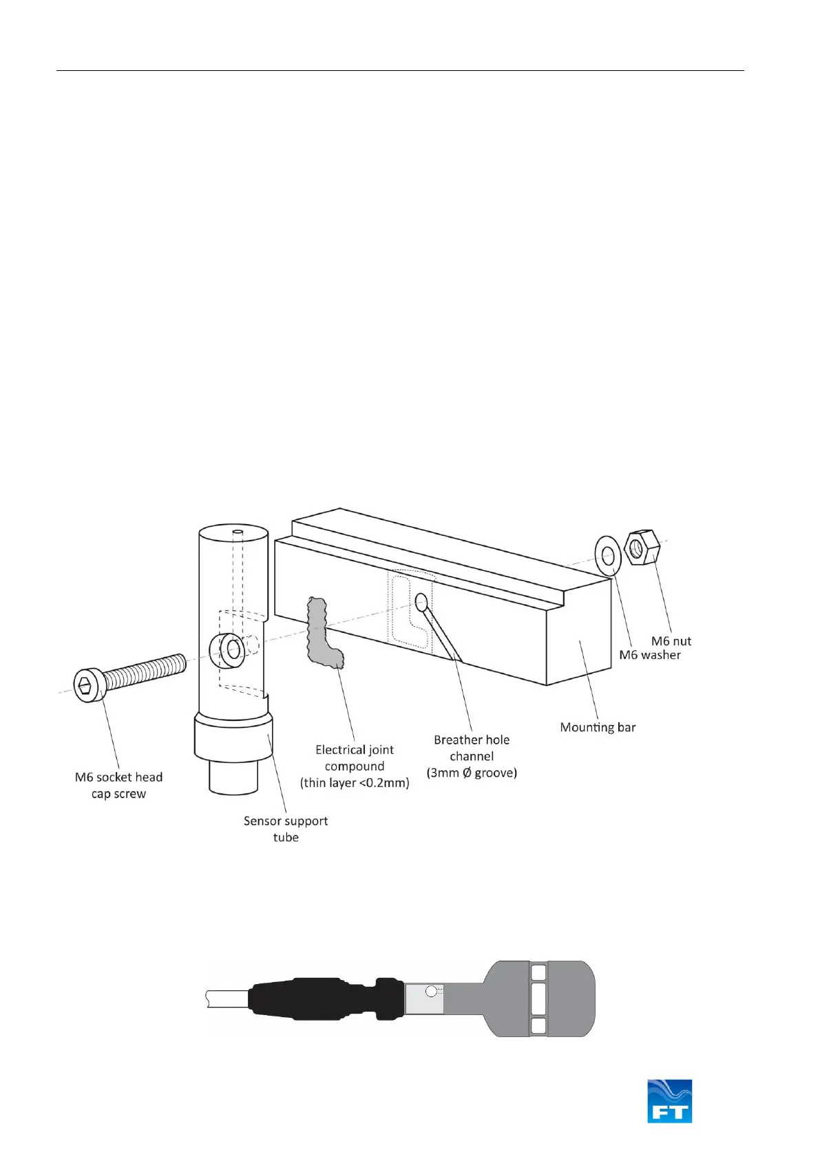
The Flat-front option is designed to be mounted using an M6 socket head cap screw, nut and washer made from
galvanised steel.
The mounting flat on the support tube of the sensor (see Figure 5) allows for firm fitting against a flat surface. The
preferred material of the mounting bar is an appropriate grade of aluminium. As an alternative hot dipped
galvanised steel can be used (aluminium is preferred as it provides superior thermal conduction in icing
conditions). If galvanised steel material is selected, the mounting bar should have a minimum galvanising
thickness of 50µm to ensure long-term protection against corrosion. The galvanising quality should conform to
ASTM A123, Standard Specification for Zinc (Hot-Dip Galvanised) Coatings on Iron & Steel Products.
The mounting flat of the sensor is provided free of coatings to allow for a good electrical connection between the
body of the sensor and ground through the mounting bar. In order to protect the mounting surface against
corrosion, a very thin layer (<0.2mm) of electrical joint compound should be applied. An example of this could be
AFL Global’s Electrical Joint Compound # 2. It should be applied directly to the sensor’s mounting surface, whilst
avoiding the fixing hole. Use of an electrical joint compound will also help to maintain long-term low impedance
connection to ground. This connection should be checked as part of a service inspection of the sensor, as detailed
in Section 4.
Some electrical joint compounds contain fluoride etchants which may react with certain materials. Material
compatibility should therefore be checked prior to application (refer to the electrical joint compound manufacturer’s
data).
In order to keep the pressure within the sensor equalised with the atmospheric pressure, a small breather hole is
located within its support tube. It is therefore important that the airway to this breather hole be kept clear. This can
be achievable by cutting a small 3mm channel in the mounting bar as shown (see Figure 5).
Figure 5: Sensor Installation
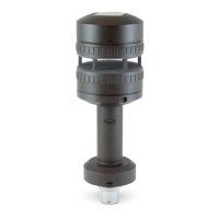
It is recommended that a protective sleeve be fitted over the base of the sensor and the connector. This will
provide environmental protection as well as stress-relief from vibration. Heat shrink or cold shrink would be
suitable for this purpose. FT offers a cold shrink solution which is available on request (part number FT909). The
sleeve should cover the lower part of the support tube, the connector itself and at least 25mm of cable (see Figure
6).
Figure 6: Flat-Front sensor with protective sleeve