Section 3 Mechanical Installation & Lightning Protection
23 FT722 & FT742 (RS485) – FF & PM Sensors – User Manual
Surge Protection
All connections from the wind sensor to any computer equipment and power supply should run through Surge
Protection Devices (SPDs). These will suppress any unwanted overvoltage transients present on the signal or
power lines. The surge suppression devices should be UL 1449 listed.
The ratings of the SPDs must be suitable for the surge conditions. Assuming that appropriate shielding and
termination has been used throughout, then the SPDs used with the sensor should have a minimum surge current
rating of 20kA (8/20µs) and be capable of clamping the output below the maximum input voltage accepted by the
electronic systems they are connected to. This will prevent any surges or large voltage differences being present
at the inputs to the wind sensor, data acquisition electronics or power supply.
The SPDs should be installed as close as possible to the point where the signals enter the cabinet in order to
prevent noise propagating to other electronics. The SPDs should also be grounded appropriately. Figure 14 shows
how the SPDs should be installed.
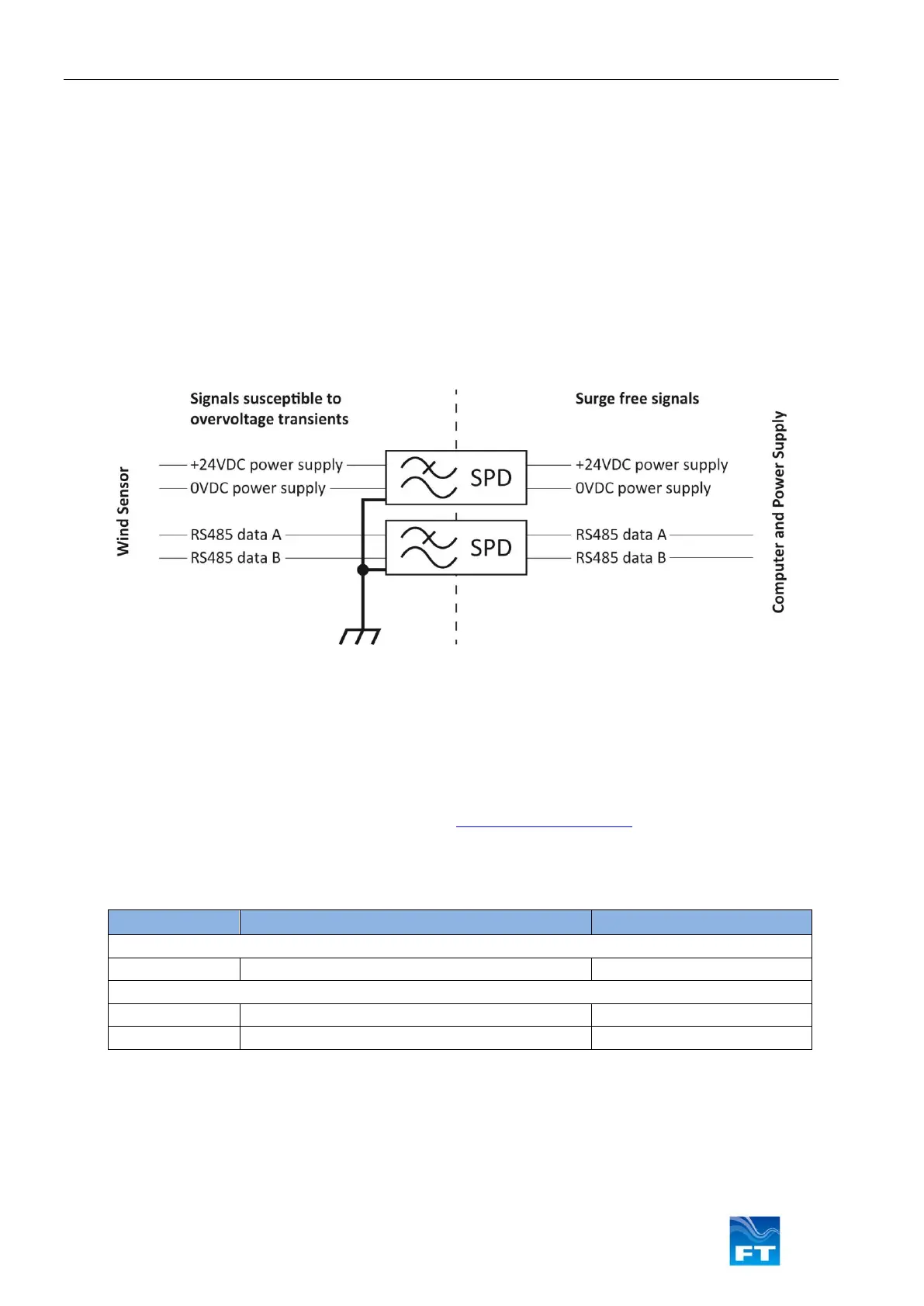
Figure 14: Digital sensor - Interface Surge Protection
The supply pair [24VDC / 0VDC] is electrically isolated from the other lines and the chassis. The triple RS-485
signal wires [Data ground, Data A, Data B] are isolated from the other lines and the chassis. The data ground can
be directly connected to the chassis of the data acquisition cabinet.
Some examples of SPDs suitable for this protection are given in Figure 15 below from manufacturers, DEHN &
Söhne GmbH. (www.dehn.de) and Phoenix Contact (www.phoenixcontact.com). Users are responsible for
ensuring the suitability of these components for their application.
Figure 15: Typical SPD configuration used to protect sensor
Figure 16 shows an example of how the wires are up the SPD’s inside a Phoenix Contact control cabinet. The
termination of the cable shield at the wall of the control cabinet using a cable gland is not shown.