SeaSTAR 3610 USER MANUAL
RECEIVER INTERFACES
Power
The 3610 DGNSS receiver will operate on any DC voltage between 9 VDC and 24
VDC. When operational, the unit dissipates typical 9 W (max 12 W) of power.
Power is connected to the unit via a 1.5 metre long red/black lead. The cable is
terminated with a 6-pin Hirose LF07WBP-6S female connector. Red is +Vin and black
is -Vin.
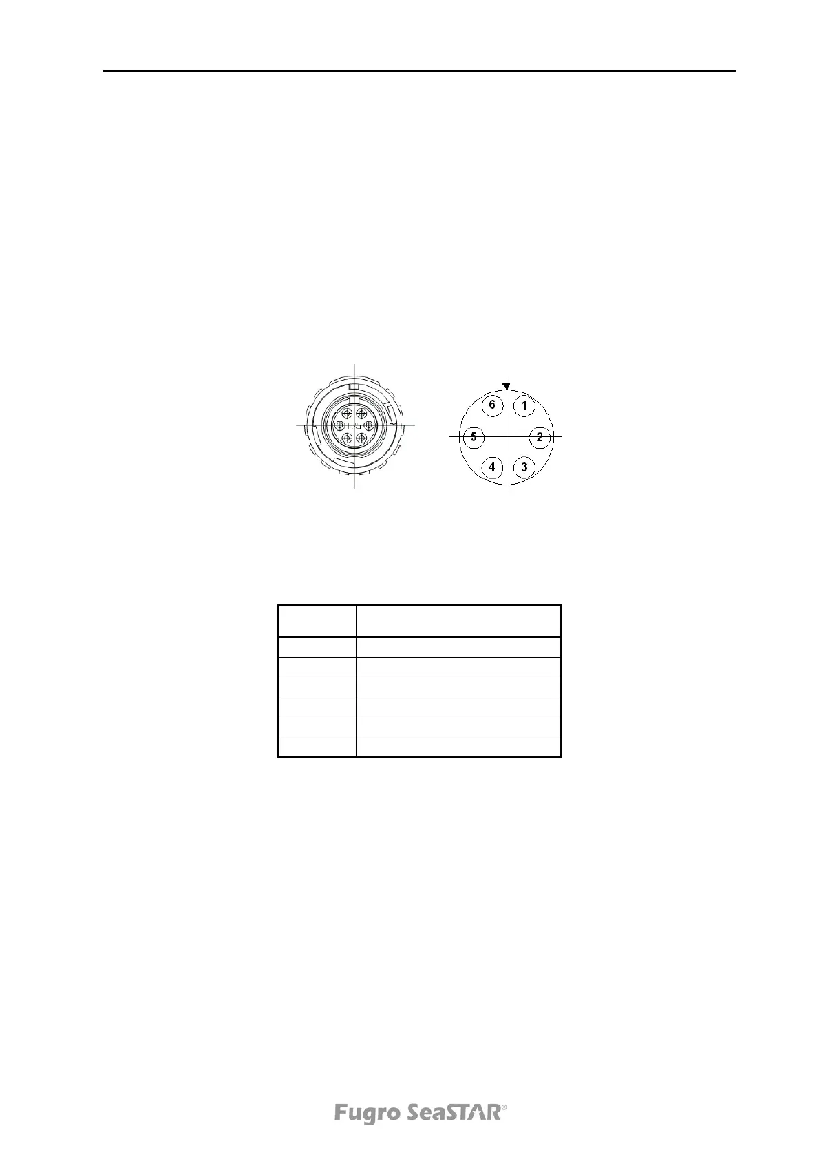
The connector pin layout is illustrated in Figure 4. Left is as viewed from the female
mating side, and right is solder side.
Figure 4. Pin layout of Hirose LF07WBP-6S female connector
The connector has the pin layout as described below:
Pin no. Signal
1 GND (Service only)
2 PPS_IN (Service only)
3 -Vin
4 -Vin
5 +Vin
6 +Vin
Table 1 Power connector pin layout
Antenna
Antenna connection is made via a low loss 50-Ohm coaxial cable (RG-223), which is
terminated with a standard N 50-Ohm male connector.
The DGNSS spotbeam antenna has an internal LNA (low noise amplifier), which is
powered by +12 VDC. The antenna can be supplied either by external power or
powered from the 3610 DGNSS receiver power (see page 15). If you use external
power, make sure to attach DC-block between the external power and the 3610
DGNSS receiver ANT connector.
Issue 2.0 02/10
9