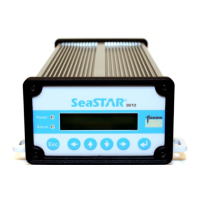
SeaSTAR 3610 USER MANUAL
INSTALLATION
Installation considerations
Before starting installation of the 3610 DGNSS receiver in a vessel, the following
should be considered:
• Determine the preferred location for each unit. The 3610 DGNSS receiver is
designed for indoor installation. Consider cable length, connector attachment
space (cable bend radius), stowing of excess cable, moisture, chemical
corrosion, vibration and heat exposure.
• Before drilling holes, consider using existing hardware and locations where
equipment has been previously installed. Avoid drilling holes that may damage
other equipment (e.g. structural frame members, electrical cables or fluid lines).
• High vibration and high temperature locations should be avoided whenever
possible.
• In applications where vibration exceeds 4Gs acceleration, shock mounts are
required. Refer to Customer support for mounting recommendations.
• All connections to the unit are at the rear side and available space for cable
connections and service must be provided.
DGNSS antenna location
Antenna positioning is critical to system performance. The following conditions must
be met for optimum system performance:
• The antenna must be mounted at least 1.5 metres away from transmitting
antennae of any frequency. Closer positioning may cause overloading of
receiver RF circuits.
• The antenna should be mounted at the highest point that will give a good view of
the horizon and be as level as possible.
Cable installation
Cables must be correctly installed for optimum system operation. Therefore, the
following should be noted:
• Recommended cable type is: 1/2" CELLFLEX
®
Superflexible Foam-Dielectric
Coaxial Cable (SCF12-50JFN) or equivalent.
• If possible, do not run L-Band receiver antenna cables parallel to other radio
system cabling closer than 30 centimetres.
• If cables must cross, ensure that they cross at an angle of 90°. This minimises
the possibility of interference.
• As far as is practicable, ensure that cables and I/O connectors are unique and fit
only in their allocated location.
• Try to make the coaxial cables as short as possible.
Issue 2.0 02/10
23