16
6mm
電線
Cable wire
pprox.
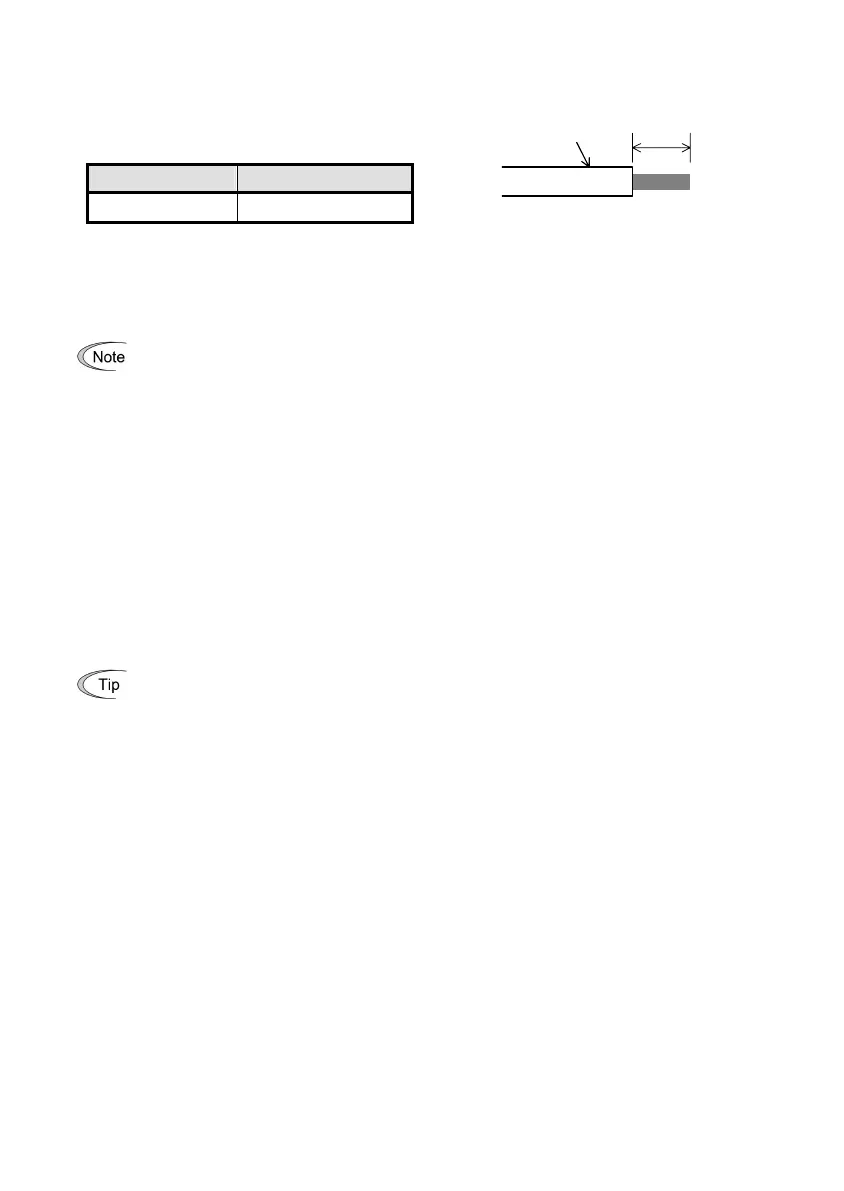
6.0 mm
Table 4.5 lists the recommended terminal screw size and its tightening torque, and Figure 4.5 shows the
recommended strip length of the cable wire end.
Table 4.5 Recommended Tightening Torque
of the Terminal Screws for the
DeviceNet Terminal Block
Terminal screw size
Tightening torque
M3 0.5 to 0.6 N·m
Figure 4.5 Recommended Strip Length of the
Cable Wire End for Terminal
Connection
(3) Terminating resistor
DeviceNet requires a terminating resistor to be installed externally on each end of the trunk line. Check that
the trunk line is terminated on both ends; if not, install a terminating resistor(s) on the missing end(s).
Terminating resistors do not come with this option. A pair of resistors with the following
specifications is separately necessary.
121 ohm ±1%, 1/4 watt, metal-film resistor
4.4 Turning ON the Optional 24 V Power Supply
Observe the following instructions about the ON/OFF timing of this option and the inverter.
(1) Power ON
It is recommended that this option be turned ON at the same time as or before the inverter. Turning the
inverter ON first may detect no operation of the option, causing a trip with
er4
alarm. The
er4
trip can be
reset after this option is turned ON.
(2) Power OFF
It is recommended that this option be turned OFF at the same time as or after the inverter. Turning the
option OFF first may cause the inverter to detect no operation of the option, causing a trip with
er4
alarm.
Turning the inverter OFF resets the
er4
trip.
When the PLC terminal on the FRENIC-Multi control circuit terminal block is used as a 24V power
source, turning ON or OFF of the inverter interlocks with that of the option. It is convenient.