17
Chapter 5 CONFIGURING INVERTER'S FUNCTION CODES FOR DeviceNet
COMMUNICATION
Before starting DeviceNet communication between the inverter equipped with this option and the DeviceNet
master device, configure the inverter's function codes listed in Table 5.1.
Table 5.2 lists other related function codes to be configured if necessary.
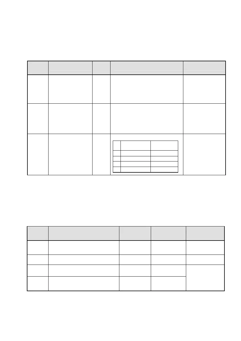
Table 5.1 Inverter's Function Codes for DeviceNet Communication
Function
codes
Description
Factory
default
setting
Function code data Remarks
o31
*1
Select output assembly
instance
(From master to slave)
0
Available data is:
20 : Basic speed control output
0, 21 : Extended speed control output
100 : Fuji drive assembly output
102 : User defined assembly output
See Chapter 7.
The factory default is
"Extended speed
control output."
o32
*1
Select input assembly
instance
(From slave to master)
0
Available data is:
70 : Basic speed control input
0, 71 : Extended speed control input
101 : Fuji drive assembly input
103 : User defined assembly input
See Chapter 7.
The factory default is
"Extended speed
control input."
y98
*2
Select run/frequency
command source
0
Available data is:
Frequency
command
Run
command
0 Inverter Inverter
1 DeviceNet Inverter
2 Inverter DeviceNet
3 DeviceNet DeviceNet
If there is no special
problem with your
system, setting y98 =
3 is recommended.
*1
After configuring the function code o31 or o32, turn the power of the inverter and the option OFF and then ON to validate the
new setting. For details about these functions, refer to Chapter 7 "I/O MESSAGE."
Input and output assembly instances should not be necessarily set to the same instance type. (Ex. Output assembly instance =
Extended speed control output, Input assembly instance = User defined assembly input.)
*2 If the extended speed control input/output is selected (o31 = 0 or 21), bit operation in the instance can select the run/frequency
command source, requiring no prior configuration of y98. For details, refer to Chapter 7, Section 7.2 "(2) Extended Speed
Control Instance."
Table 5.2 Other Related Function Codes
Function
codes
Description
Factory default
setting
Function code
setting range
Remarks
o27
*1
Select the inverter’s operation mode to
apply when a DeviceNet
communications error occurs.
0 0 to 15
o28
*1
Set the operation timer to apply when a
DeviceNet communications error occurs.
0.0 s 0.0 to 60.0 s
o40 to o43
*2
Assign the function code writing data
cyclically.
0
(No assignment)
0000 to FFFF (hex)
o48 to o51
*2
Assign the function code reading data
cyclically.
0
(No assignment)
0000 to FFFF (hex)
Valid only when
"User defined
assembly
input/output" is
selected (o31 = 102,
o32 = 103).
*1 For details about function codes o27 and o28, refer to Chapter 9 "INVERTER REACTION TO DeviceNet COMMUNICATIONS
ERRORS."
*2 For details about function codes o40 to o43 and o48 to o51, refer to Chapter 7, Section 7.2 (4) "User Defined Assembly
Instance."