EasyManua.ls Logo

Fuji Electric FRENIC-Multi OPC-E1-DEV User Manual

Fuji Electric FRENIC-Multi OPC-E1-DEV
42 pages
To Next Page IconTo Next Page
To Previous Page IconTo Previous Page
Page #30 background imageLoading...
Page #30 background image
28
Chapter 8 EXPLICIT MESSAGE
8.1 Overview
Explicit Message is a communication process that accesses DeviceNet variables at arbitrary (event-driven)
timing. Using this option is capable of accessing not only standard DeviceNet variables but also all inverter's
function codes. Explicit Message lacks realtime performance, but it allows many variables to be set or referred
to. It is, therefore, suited for initial setting.
Refer to the user's manual of the connected master for Explicit Message.
- Variables usable in Explicit Message are grouped using three codes--Class (major key), Instance
(medium key) and Attribute (minor key). These three codes should be used for specifying a variable.
- A group of all variables contained in Class is called "Object."
8.2 Objects to be Used in Explicit Message
This section describes objects relating to this option and the inverter. Other objects that are automatically
executed by the master device are excluded in this manual.
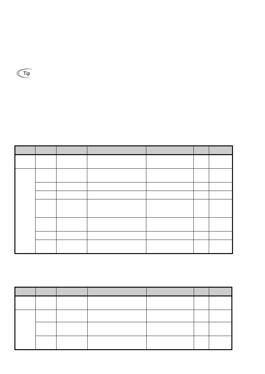
(1) Identity object (Class 01 hex.)
This object refers to the product information of this option. It is a group of read-only variables.
Instance Attribute Name Description Value (hex.) R/W Data size
0 01 Revision Revision number of Identity
object
0001 R Word
1 01 Vender ID Manufacturer's ID code 013F (=319):
Fuji Electric
R Word
02 Device Type Applied device profile 0002: AC drive R Word
03 Product Code ID code of this option 2402 R Word
04 Revision Software version
(Major and minor versions)
Display of version
Example: 01, 0A
(=Ver. 1.10)
R Byte,
Byte
05 Status Status of this option Depends on DeviceNet
specifications.
R Word
06 Serial Number Serial number of the product Differs with the product. R DWord
07 Product Name Model name
OPC-E1-DEV R 11 bytes
(2) Motor Data object (Class 28 hex.)
This object refers to and sets up the motor rated current and voltage. When Motor 2 is selected, this object
automatically switches to the one for Motor 2.
Instance Attribute Name Description Value (hex.) R/W Data size
0 01 Revision Revision number of Motor
Data object
0001 R Word
1 03 Motor Type Type of motor connected 07: Squirrel-cage,
induction motor
R Byte
06 Rated
Current
Rated current in units of 0.1 A Depends on the
inverter setting.
R/W Word
07 Rated
Voltage
Rated voltage in units of 1 V
(base voltage)
Depends on the
inverter setting.
R/W Word

Questions and Answers:

Fuji Electric FRENIC-Multi OPC-E1-DEV Specifications

General IconGeneral
BrandFuji Electric
ModelFRENIC-Multi OPC-E1-DEV
CategoryControl Unit
LanguageEnglish

Summary

Preface

How this manual is organized

Overview of the manual's chapter structure and content.

Related Publications

Lists other manuals relevant to the DeviceNet interface option.

Safety precautions

Details important safety information and warnings for using the product.

Operational Procedures

Installation and Wiring

Instructions for installing and wiring the DeviceNet interface option.

Operation

Guidance on operating the inverter with the DeviceNet interface option.

Maintenance and Inspection

Procedures for maintaining and inspecting the DeviceNet option.

Disposal

Others

Chapter 1: Before Using This Option

1.1 Acceptance Inspection

Checks to be performed upon delivery of the DeviceNet interface option and accessories.

1.2 Applicable Inverters

Lists the FRENIC-Multi inverters and ROM versions compatible with the option.

Chapter 2: Basic Functions and Settings

2.1 DeviceNet Interface Option Inside View

Illustrates the internal components of the DeviceNet interface option.

2.2 DIP Switch

Configures communication data rate and node address using the DIP switch.

2.3 LED Status Indicators

Details the meaning of the MS and NS LEDs indicating hardware and network status.

2.4 RJ-45 Connector and Terminal Blocks

Covers RJ-45 connector and terminal blocks for power and DeviceNet connections.

Chapter 3: Installation of This Option

Chapter 4: Wiring and Cabling

4.1 Basic Connection Diagram

Illustrates the fundamental wiring connections for the FRENIC-Multi and DeviceNet option.

4.2 Wiring for Power Supply Terminal Block

Details the wiring procedures for the 24V power supply terminal block.

4.3 Wiring for DeviceNet Terminal Block

Explains the wiring connections for the DeviceNet communication cable.

4.4 Turning ON the Optional 24 V Power Supply

Provides instructions on the correct ON/OFF timing for the option and inverter.

Chapter 5: Configuring Inverter's Function Codes for DeviceNet Communication

Chapter 6: Establishing a DeviceNet Communications Link

Chapter 7: I/O Message

7.1 Overview

Explains I/O Message as a cyclic communication process between master and slave.

7.2 I/O Assembly Instances: Selection and Setup

Details the selection and setup of I/O assembly instances for various control modes.

7.3 An Example of Actual I/O Communication Data

Provides a practical example of I/O data in Extended Speed Control Instance.

Chapter 8: Explicit Message

8.1 Overview

Explains Explicit Message for arbitrary access to DeviceNet variables and function codes.

8.2 Objects to be Used in Explicit Message

Describes objects related to the option and inverter for explicit message communication.

8.3 Error Code List for Explicit Message Errors

Lists explicit message errors, their codes, descriptions, and recovery methods.

Chapter 9: Inverter Reaction to DeviceNet Communications Errors

Chapter 10: Alarm Code List

Chapter 11: Troubleshooting

Chapter 12: Specifications

12.1 General Specifications

Lists general specifications of the DeviceNet interface option and applicable inverter.

12.2 DeviceNet Specifications

Details the specifications related to DeviceNet communication protocols and capabilities.

Related product manuals