5-36
Function (F31)㩷
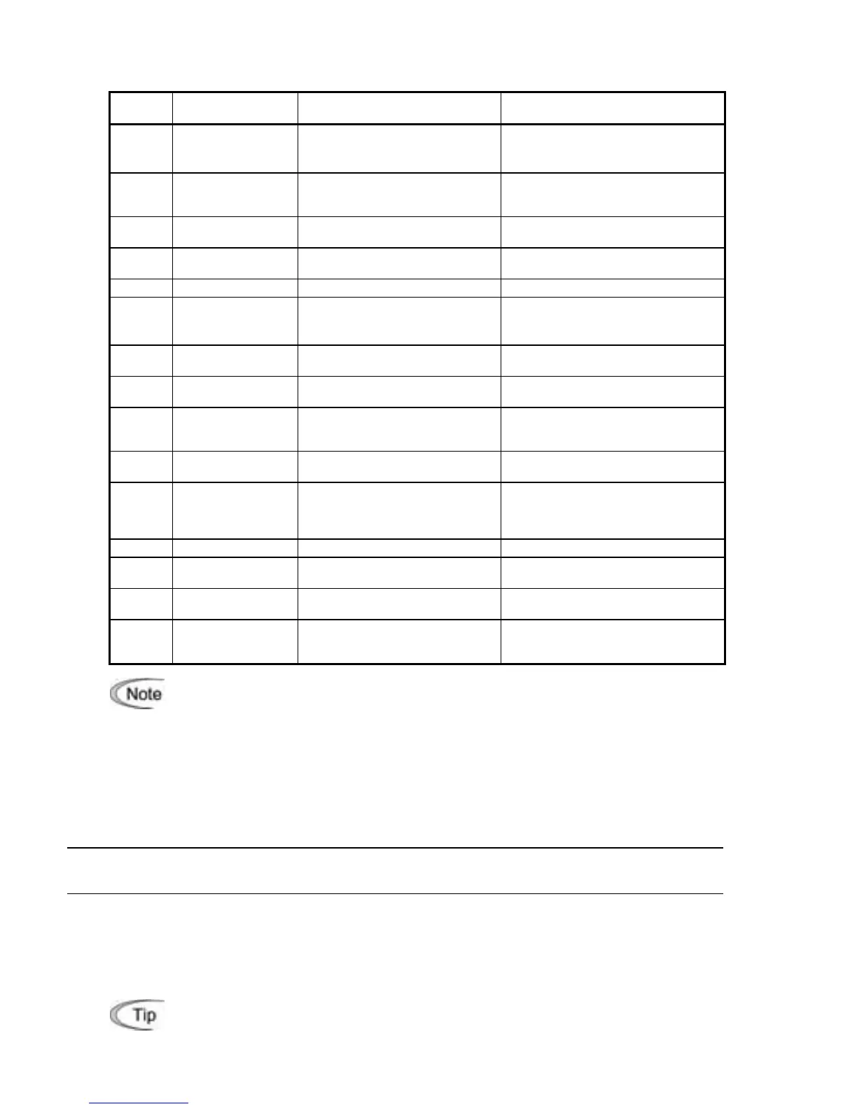
F31 specifies what is output to analog output terminal [FM].
Data for
F31
[FM] output
Function
(Monitor the following)
Meter scale
(Full scale at 100%)
0
Output frequency
(before slip
compensation)
Output frequency of the inverter
(Equivalent to the motor
synchronous speed)
Maximum frequency (F03/A01)
1
Output frequency
(after slip
compensation)
Output frequency of the inverter Maximum frequency (F03/A01)
2 Output current
Output current (RMS) of the
inverter
Twice the inverter rated current
3 Output voltage
Output voltage (RMS) of the
inverter
250 V for 230 V class series,
500 V for 460 V class series
4 Output torque Motor shaft torque Twice the rated motor torque
5 Load factor
Load factor
(Equivalent to the indication of
the load meter)
Twice the rated motor load
6 Input power Input power of the inverter
Twice the rated output of the
inverter
7
PID feedback
amount (PV)
Feedback amount under PID
control
100% of the feedback amount
8 PG feedback value
Feedback value of closed loop
control through the PG
interface
Maximum speed
(100% of the feedback value)
9
DC link bus
voltage
DC link bus voltage of the
inverter
500 V for 230 V class series,
1000 V for 460 V class series
10 Universal AO
Command via communications
link (Refer to the RS-485
Communication User's
Manual.)
20000 as 100%
13 Motor output Motor output (kW) Twice the rated motor output
14 Calibration
Full scale output of the meter
calibration
This always outputs the full-scale
(100%).
15
PID command
(SV)
Command value under PID
control
100% of the feedback amount
16 PID output (MV)
Output level of the PID
controller under PID control
(Frequency command)
Maximum frequency (F03/A01)
If F31 = 16 (PID output), J01 = 3 (Dancer control), and J62 = 2 or 3 (Ratio
compensation enabled), the PID output is equivalent to the ratio against the primar
displays the PID output in a converted absolute value. To indicate the value up to
the full-scale of 300%, set F30 data to "33" (%).
Pulse rate (F33) dedicated to FMP㩷
F33 specifies the number of pulses at which the output of the monitored item selected
reaches 100%, in accordance with the specifications of the counter to be connected.
F40, F41
E16, E17
Torque Limiter 1 (Limiting levels for driving and braking)
Torque Limiter 2 (Limiting levels for driving and braking)
If the inverter’s output torque exceeds the specified levels of the driving torque limiter
(F40/E16) and the braking torque limiter (F41/E17), the inverter controls the output frequency
and limits the output torque for preventing a stall.
Specify the limiting levels at which the torque limiter becomes activated, as the percentage of
the motor rated torque.
To switch the inverter’s output torque limiter between torque limiter 1 (F40/F41) and
torque limiter 2 (E16/E17), use the terminal command TL2/TL1 assigned to a digital
input terminal. (Refer to the descriptions of E01 to E05.)
 Loading...


