5-37
The torque limiter and current limiter are very similar function each other. If both are
activated concurrently, they may conflict each other and cause a hunting in the
system. Avoid concurrent activation of these limiters.
F42
H68
Control Mode Selection 1
Slip Compensation 1 (Operating conditions)
F42 specifies the control mode of the inverter to control a motor.
Data for F42 Control mode
0 V/f control with slip compensation inactive
1 Dynamic torque vector control
2 V/f control with slip compensation active
3 V/f control with optional PG interface
4 Dynamic torque vector control with optional PG interface
V/f control㩷
In this control, the inverter controls a motor by the voltage and frequency according to the V/f
pattern specified by function codes.
Slip compensation㩷
Applying any load to an induction motor causes a rotational slip due to the motor
characteristics, decreasing the motor rotation. The inverter’s slip compensation facility first
presumes the slip value of the motor based on the motor torque generated and raises the
output frequency to compensate for the decrease in motor rotation. This prevents the motor
from decreasing the rotation due to the slip.
That is, this facility is effective for improving the motor speed control accuracy.
The compensation value is specified by combination of function codes P12 (Rated slip
frequency), P09 (Slip compensation gain for driving) and P11 (Slip compensation gain for
braking).
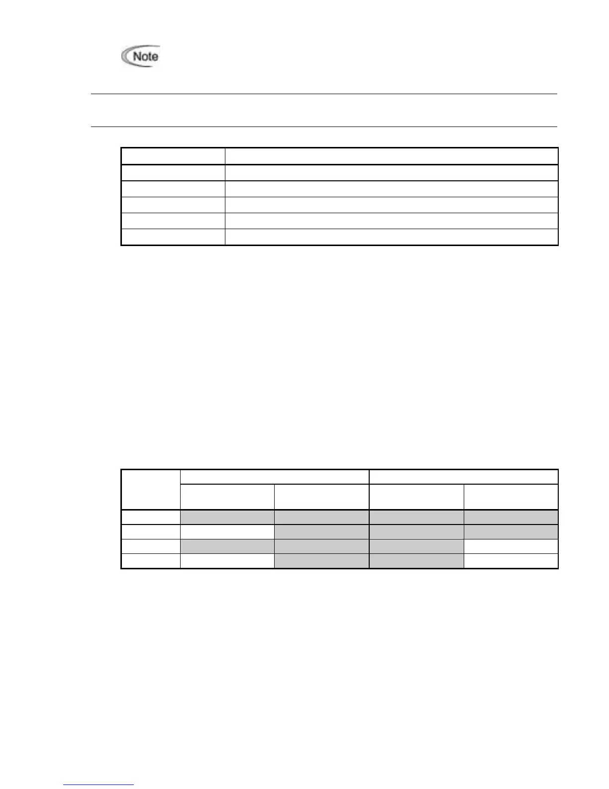
H68 enables or disables the slip compensation facility according to the motor driving
conditions.
Motor driving conditions Motor driving frequency zone
Data for
H68
Accl/Decel Constant speed
Base frequency
or below
Above the base
frequency
0 Enable Enable Enable Enable
1 Disable Enable Enable Enable
2 Enable Enable Enable Disable
3 Disable Enable Enable Disable
Dynamic torque vector control㩷
To get the maximal torque out of a motor, this control calculates the motor torque for the load
applied and uses it to optimize the voltage and current vector output.
Selecting this control automatically enables the auto torque boost and slip compensation
function and disables auto energy saving operation. Using the PG feedback speed control at
same time, however, also disables the slip compensation function.
This control is effective for improving the system response against external disturbances and
the motor speed control accuracy.
PG speed feedback control (PG interface)㩷
This control is made available by mounting an optional pulse generator (PG) interface card.
It uses the speed feedback from the PG on the motor shaft to control the motor speed with
high accuracy.
 Loading...


