5-38
In the slip compensation and dynamic torque vector control, the inverter uses the
motor parameters to control its speed. Therefore, the following conditions should be
satisfied; if not, the inverter may not get the proper performance from the motor.
• A single motor should be controlled. (It is difficult to apply this control to a group
motor driving system.)
• Motor parameters P02, P03 and P06 to P12 are properly configured or they are
fully auto-tuned.
• The rating of the motor to be controlled should be two ranks lower than that of the
inverter. If not, the output current detection sensibility of the motor lowers, causing
it difficult to accurately control the motor.
• The wiring between the inverter output and motor input terminals should not
exceed 50 m in length. A long wiring run could not suppress the earth leakage
current since the cable's electrostatic capacitance against the earth increases,
causing it difficult to accurately control the motor speed.
F43, F44 Current Limiter (Mode selection, Level)
When the output current of the inverter exceeds the level specified by the current limiter (F44),
the inverter automatically manages its output frequency to prevent a stall and limit the output
current. (Refer to the description of function code H12.)
If F43 = 1, the current limiter is enabled only during constant speed operation. If F43 = 2, the
current limiter is enabled during both of acceleration and constant speed operation. Choose
F43 = 1 if you need to run the inverter at full capability during acceleration and to limit the
output current during constant speed operation.
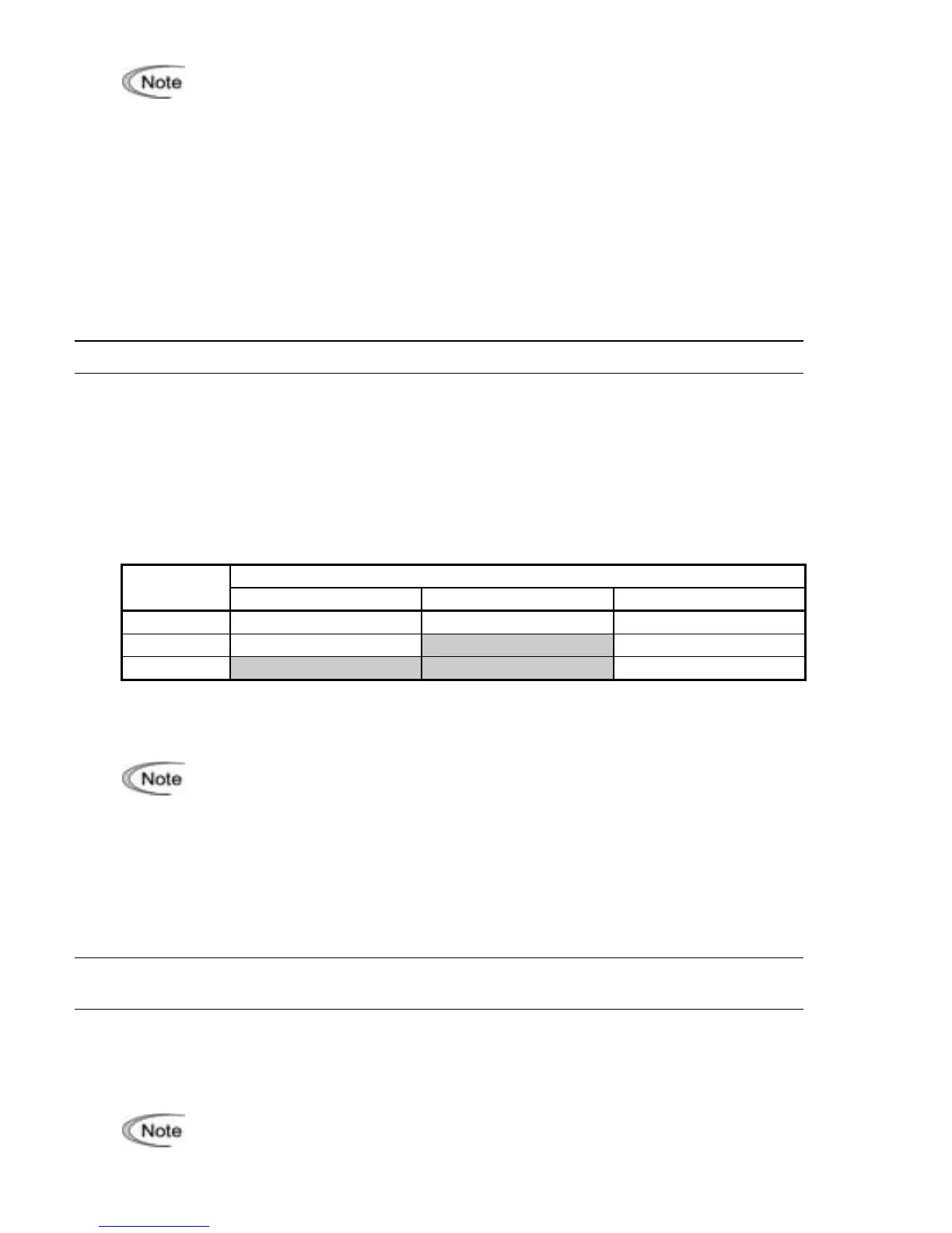
Mode selection (F43)㩷
F43 selects the motor running state in which the current limiter will be active.
Running states that enable the current limiter
Data for
F43
During acceleration During constant speed During deceleration
0 Disable Disable Disable
1 Disable Enable Disable
2 Enable Enable Disable
Level (F44)㩷
F44 specifies the operation level at which the output current limiter becomes activated, in ratio
to the inverter rating.
• Since the current limit operation with F43 and F44 is performed by software, i
extremely low, the inverter will rapidly lower its output frequency. This may cause
an overvoltage trip or dangerous turnover of the motor rotation due to
undershooting.
• The torque limiter and current limiter are very similar function each other. If both
are activated concurrently, they may conflict each other and cause a hunting in
the system. Avoid concurrent activation of these limiters.
F50, F51
Electronic Thermal Overload Protection for Braking Resistor
(Discharging capability and Allowable average loss)
These function codes specify the electronic thermal overload protection feature for the
braking resistor.
Set F50 and F51 data to the discharging capability and allowable average loss, respectively.
Those values differ depending on the specifications of the braking resistor, as listed on the
following pages.
Depending on the thermal marginal characteristics of the braking resistor, the
electronic thermal overload protection feature may act so that the inverter issues the
overheat protection alarm
FDJ
even if the actual temperature rise is not enough. If it
happens, review the relationship between the performance index of the braking
resistor and settings of related function codes.
 Loading...


