5-42
Terminal function assignment and data setting
Select multi-frequency (0 to 15 steps) -- SS1, SS2, SS4, and SS8
(Function code data = 0, 1, 2, and 3)㩷
The combination of the ON/OFF states of digital input signals SS1, SS2, SS4 and SS8 selects
one of 16 different frequency commands defined beforehand by 15 function codes C05 to C19
(Multi-frequency 0 to 15). With this, the inverter can drive the motor at 16 different preset
frequencies.
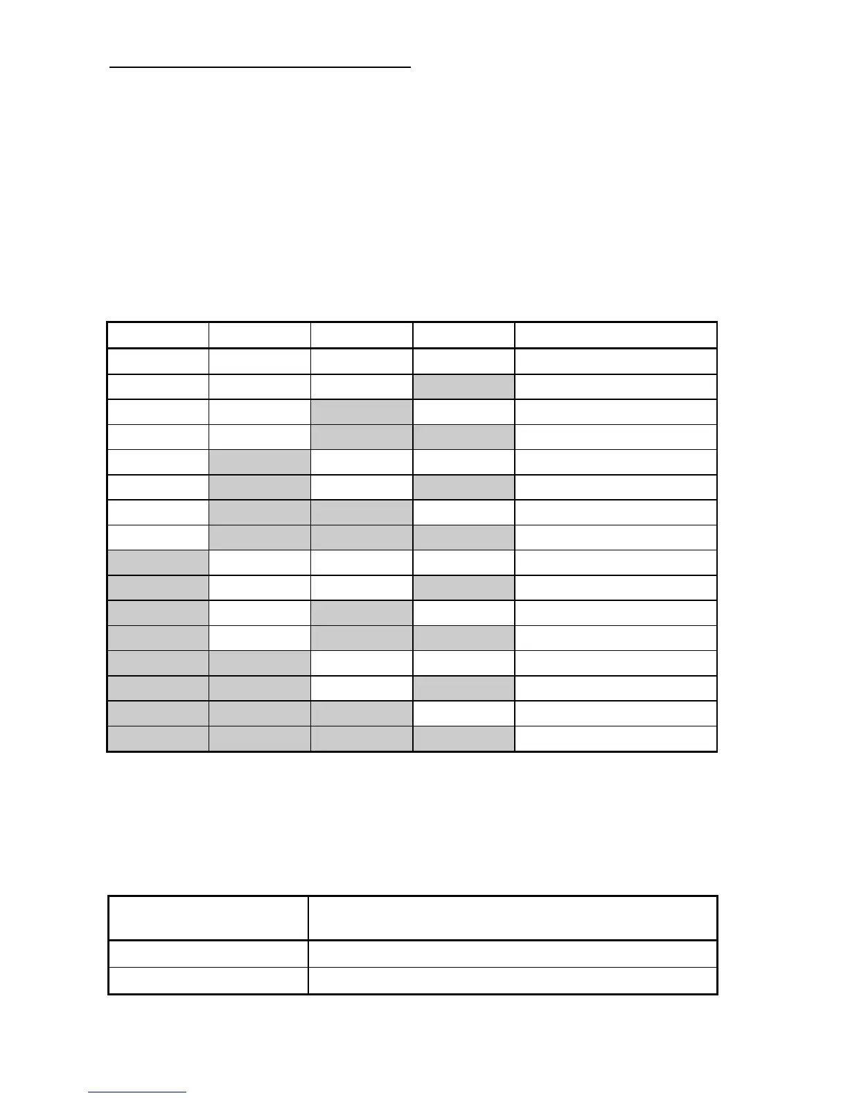
The table below lists the frequencies that can be obtained by the combination of switching
SS1, SS2, SS4 and SS8. In the "Selected frequency" column, "Other than multi-frequency"
represents the reference frequency sourced by frequency command 1 (F01), frequency
command 2 (C30), or others. For details, refer to the block diagram in FRENIC-Multi User's
Manual, Chapter 4, Section 4.2 "Drive Frequency Command Block."
SS8 SS4 SS2 SS1 Selected frequency
OFF OFF OFF OFF Other than multi-frequency
OFF OFF OFF ON C05 (Multi-frequency 1)
OFF OFF ON OFF C06 (Multi-frequency 2)
OFF OFF ON ON C07 (Multi-frequency 3)
OFF ON OFF OFF C08 (Multi-frequency 4)
OFF ON OFF ON C09 (Multi-frequency 5)
OFF ON ON OFF C10 (Multi-frequency 6)
OFF ON ON ON C11 (Multi-frequency 7)
ON OFF OFF OFF C12 (Multi-frequency 8)
ON OFF OFF ON C13 (Multi-frequency 9)
ON OFF ON OFF C14 (Multi-frequency 10)
ON OFF ON ON C15 (Multi-frequency 11)
ON ON OFF OFF C16 (Multi-frequency 12)
ON ON OFF ON C17 (Multi-frequency 13)
ON ON ON OFF C18 (Multi-frequency 14)
ON ON ON ON C19 (Multi-frequency 15)
Select ACC/DEC time -- RT1 (Function code data = 4)㩷
This terminal command switches between ACC/DEC time 1 (F07/F08) and ACC/DEC time 2
(E10/E11).
If no RT1 command is assigned, ACC/DEC time 1 (F07/F08) takes effect by default.
Input terminal command
RT1
Acceleration/deceleration time
OFF Acceleration/deceleration time 1 (F07/F08)
ON Acceleration/deceleration time 2 (E10/E11)