5-71
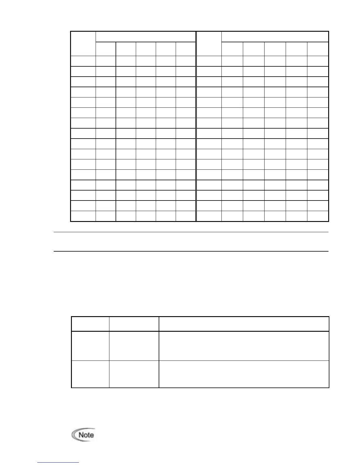
Conversion table (Decimal to/from binary)
Binary Binary
Decimal
Bit 4 Bit 3 Bit 2 Bit 1 Bit 0
Decimal
Bit 4 Bit 3 Bit 2 Bit 1 Bit 0
0 0 0 0 0 0 16 1 0 0 0 0
1 0 0 0 0 1 17 1 0 0 0 1
2 0 0 0 1 0 18 1 0 0 1 0
3 0 0 0 1 1 19 1 0 0 1 1
4 0 0 1 0 0 20 1 0 1 0 0
5 0 0 1 0 1 21 1 0 1 0 1
6 0 0 1 1 0 22 1 0 1 1 0
7 0 0 1 1 1 23 1 0 1 1 1
8 0 1 0 0 0 24 1 1 0 0 0
9 0 1 0 0 1 25 1 1 0 0 1
10 0 1 0 1 0 26 1 1 0 1 0
11 0 1 0 1 1 27 1 1 0 1 1
12 0 1 1 0 0 28 1 1 1 0 0
13 0 1 1 0 1 29 1 1 1 0 1
14 0 1 1 1 0 30 1 1 1 1 0
15 0 1 1 1 1 31 1 1 1 1 1
J63 to J67
Overload Stop
(Detection value, Detection level, Mode selection, Operation condition and Timer)
When the monitored status index of the load exceeds the detection level specified by J64 for
the period specified by J67, the inverter activates the overload stop function according to
operation specified by J65. Use this function for such as system protection from applying a
load that cannot be allowed by the system characteristics or any reason on the system design
or system in which the motor spindle is locked by a mechanical stopper.
Detection value (J63)
J63 specifies the detection value of status index to be monitored.
Data for J63
Detection value Description
0 Output torque
To improve the accuracy of torque calculation, be sure to
auto-tune the inverter for the applied motor.
This setting covers the driving torque only.
1 Output current
The no-load current to the motor always flows. Specify J64
(Detection level) correctly considering the no-load current of
the applied motor.
Detection level (J64)
J64 specifies the detection level assuming the inverter rated current and motor rated torque
as 100%.
When J65 = 3 (Hit and stop), the detection level (J64) is determined based on not
the J63 data but the motor rated toque.