5-70
Input phase loss protection (
NKP
) (Bit 1)
Upon detection of an excessive stress inflicted on the apparatus connected to the main circuit
due to phase loss or line-to-line voltage unbalance in the three-phase power supplied to the
inverter, this feature stops the inverter and displays an alarm
NKP
.
In configurations where only a light load is driven or a DC reactor is connected,
phase loss or line-to-line voltage unbalance may not be detected because of the
relatively small stress on the apparatus connected to the main circuit.
Output phase loss protection (
RN
) (Bit 2)
Upon detection of phase loss in the output while the inverter is running, this feature stops the
inverter and displays an alarm
RN
. Where a magnetic contactor is installed in the inverter
output circuit, if the magnetic contactor goes OFF during operation, all the phases will be lost.
In such a case, this protection feature does not work.
Judgment threshold on the life of DC link bus capacitor (Bit 3)
Bit 3 is used to select the threshold for judging the life of the DC link bus capacitor between
factory default setting and your own choice.
Before specifying the threshold of your own choice, measure and confirm the
reference level in advance.
Judgment on the life of DC link bus capacitor (Bit 4)
Whether the DC link bus capacitor has reached its life is determined by measuring the length
of time for discharging after power OFF. The discharging time is determined by the
capacitance of the DC link bus capacitor and the load inside the inverter. Therefore, if the load
inside the inverter fluctuates significantly, the discharging time cannot be accurately
measured, and as a result, it may be mistakenly determined that the life has been reached. To
avoid such an error, you can disable the judgment on the life of the DC link bus capacitor.
Since load may vary significantly in the following cases, disable the judgment on the life
during operation. Either conduct the measurement with the judgment enabled under
appropriate conditions during periodical maintenance or conduct the measurement under the
operating conditions matching the actual ones.
• An option card or multi-function keypad is used.
• Another inverter or equipment such as a PWM converter is connected to the terminals of
the DC link bus.
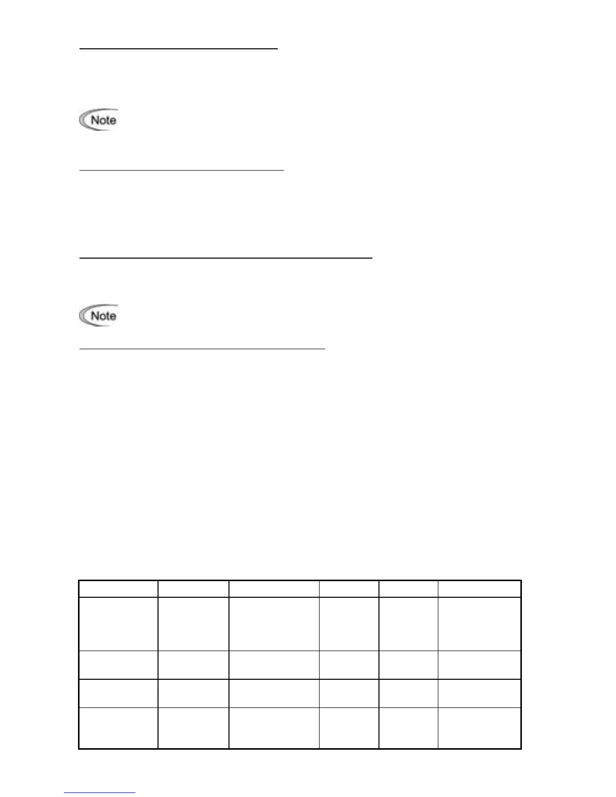
To set data of H98, assign functions to each bit (total 5 bits) and set it in decimal format. The
table below lists functions assigned to each bit.
Bit number Bit 4 Bit 3 Bit 2 Bit 1 Bit 0
Function
Judge the life
of DC link bus
capacitor
Select life
judgment
threshold of DC
link bus capacitor
Detect
output
phase loss
Detect
input
phase loss
Lower the
carrier
frequency
automatically
Data = 0 Disable
Use the factory
default
Disable Disable Disable
Data = 1 Enable
Use the user
setting
Enable Enable Enable
Example of
decimal
expression (19)
Enable (1)
Use the factory
default (0)
Disable (0) Enable (1) Enable (1)