– 12 –
3 Usage (Read before using)
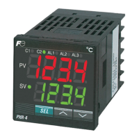
Name of Functional Parts and Functions
AL2AL1C1 C2 AL3
SEL
PXR-4
SV
PV
1
2
3
S1 S2 S3
4
8
765
Model : PXR4
Name Function
Select key The key shifting to the 1st, the 2nd or the 3rd block parameter, switching the display
between parameter and the data at the 1st, the 2nd and the 3rd block.
Setting keys
S1
Down key · The numerical value is decreased by pressing the key once. The numerical value
keeps on decreasing by pressing the key continuously.
· For searching parameters within the 1st, the 2nd and the 3rd block.
S3
Up key · The numerical value is increased by pressing the key once. The numerical value
keeps on increasing by pressing the key continuously.
· For searching parameters within the 1st, the 2nd and the 3rd block.
S2
Name Function
Process value (PV)/parameter
name display
1) Displays a process value (PV).
2) Displays the parameter symbols at parameter setting mode.
3) Displays various error indications (refer to the “8. Error indications”).
Display/Indication
q
Auto-tuning/self-tuning indicator/
manual operation
r
Set value (SV) indication lamp
w
Control output indication lamp
The lamp is lit while a set value (SV) is displayed.
Set value (SV)/parameter setting
display
e
1) Displays a set value (SV).
2) Display the parameter settings at parameter setting mode.
3) Flickers at Standby mode.
4) Displays the set value (SV ) and “SV-1” alternately when the SV
witching function is used.
5) Displays the set value (SV) and “rSV” alternately while in remote
operation.
The lamp flickers while the PID auto-tuning or the self-tuning is being
performed.
Kept on during manial operation.
t
Alarm output 1 (AL1)
indication lamp (Note 1)
C1 : The lamp is lit while the control output 1 is ON.
C2 : The lamp is lit while the control output 2 is ON. (Note 1)
y
Alarm output 2 (AL2)
indication lamp (Note 1)
The lamp is lit when the alarm output 1 is activated.
It flickers during ON-delay operation. (Note 2)
u
The lamp is lit when the alarm output 2 is activated.
It flickers during ON-delay operation. (Note 2)
Alarm output 3 (AL3)
indication lamp (Note 1)
i
The lamp is lit while the alarm output 3 or the heater break alarm
output is ON. The lamp flickers while in ON delay operation. (Note 2)
Note 1) Control output 2 and alarm function are optional.
Note 2) The lamp does not flicker while the timer is activated.
 Loading...


