Do you have a question about the Fuji Electric PXR4 and is the answer not in the manual?
Lists associated manuals and their document numbers for further reference.
Highlights critical safety risks associated with uncontrolled heating and potential system failures.
Details safety requirements for controller installation and electrical wiring to prevent hazards.
Provides essential guidelines for maintaining the controller to ensure safety and longevity.
Advises on avoiding specific environmental conditions and locations that could compromise controller performance or safety.
Explains the correct method for mounting the controller onto a panel, emphasizing waterproofness and secure fitting.
Outlines critical steps and considerations for safe and effective wiring connections to prevent noise and ensure reliability.
Guides users on checking alarm functions and handling input errors or sensor replacement procedures.
Provides advice on cleaning the controller and general operational considerations.
Presents the physical dimensions of the controller and the required panel cutout for installation.
Advises on specific requirements and limitations when installing multiple controllers adjacent to each other.
Offers specific guidance on starting wiring from the correct terminals and using appropriate connectors for secure connections.
Illustrates the complete wiring diagram, showing connections for power, alarms, inputs, and outputs.
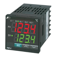
Identifies and describes the purpose of each key component and indicator on the controller's front panel.
Explains the operation of the S1, S2, and S3 keys for navigating parameters and adjusting values.
Details the meaning of various displays and indicator lamps on the controller, including PV, SV, and output status.
Describes the controller's behavior and limitations when operating in standby mode.
Guides users on changing set values (SV) and shifting between parameter blocks (1st, 2nd, 3rd) using the SEL key.
Outlines the step-by-step procedure for entering parameter setting mode and modifying parameter values.
Illustrates the controller display states for Auto, Manual, and Standby operational modes.
Details parameters related to operation mode, auto-tuning, control mode, and alarm settings.
Covers parameters for PID control, input types, alarm settings, and ramp/soak functions.
Includes parameters for control action, delay times, hysteresis, digital inputs, and communication settings.
Explains the basic ON/OFF control mode, including parameter settings for hysteresis to prevent chattering.
Describes the process and conditions for automatic calculation and optimization of PID parameters.
Details how self-tuning automatically re-optimizes PID parameters based on process conditions and provides setting instructions.
Introduces different alarm types (absolute, deviation, zone) and explains functions like ON delay and de-energizing.
Lists specific parameters for configuring alarm hysteresis, ON delay, latching, error status, and de-energizing.
Explains possible combinations of alarm functions and provides critical cautions for their effective use.
Describes how the set value (SV) changes over time according to a programmed pattern.
Guides on selecting program patterns and setting the run mode for ramp/soak operations.
Explains that internal data can be read/written via MODBUS or ASCII communications.
Details the required parameters (Station No., Parity, Protocol) for setting up communication.
Provides important notes on station number range, parity settings, and baud rate.
Lists available functions that can be controlled via digital inputs, such as SV switching and auto-tuning start.
Explains how to select specific functions using DI function codes for parameters di-1 and di-2.
Provides a detailed mapping of DI function codes to specific controller actions and descriptions.
Introduces bAL (offset) and Ar (integral range) for suppressing overshoot and improving control.
Details the procedure to make the bAL and Ar parameters visible or hidden in the settings.
Explains how to set the output type and scaling for re-transmission of PV, SV, MV, or DV signals.
Describes how the set value (SV) can be controlled by external 1-5V voltage signals.
Guides on connecting the remote SV signal, adjusting zero/span points, and switching to remote operation mode.
Details how to select the correct sensor input type (Thermocouple, RTD, Voltage, Current) using the P-n2 parameter.
Explains how to set the lower and upper limits (P-SL, P-SU) for the selected input range to match the application.
Covers selecting control output actions (Heating/Cooling) and control algorithms (ON/OFF, PID, Fuzzy) with self-tuning.
Lists common error codes (UUUU, LLLL, Err), their possible causes, and control outputs during error conditions.
Details front dimensions and options for selecting input signal types and ranges.
Explains the selection of control output types (Relay, Pulse, 4-20mA) and optional specifications.
Covers optional features like alarms, ramp/soak, digital inputs, and RS485 communication settings.
Details power supply voltage options and instruction manual language selections.
Provides important notes and conditions related to specific model code combinations and installation requirements.
| Brand | Fuji Electric |
|---|---|
| Model | PXR4 |
| Category | Microcontrollers |
| Language | English |