– 17 –
3rd block parameter
Parameter
Control action
Description of contents
Default
setting
Remarks
P-n1
A1hY
A2hY
dLY2
A1oP
A2oP
dLY1 ON delay time of
alarm 1
ON delay time of
alarm 2
Additional function
of alarm 2
Additional function
of alarm 1
Lower limit of SV
(Setting range: 0 to 100%FS)
Lower limit of SV
Upper limit of SV
(Setting range: 0 to 100%FS)
Upper limit of SV
0%FS
100%FS
SV-L
SV-H
0/4 Table 2
(Page 31)
Note 2
6-7
(Page 25)
6-6
(Page 24)
Hysteresis for
alarm 1
Sets ON-OFF hysteresis for alarm output.
(Setting range: 0 to 50%FS)
1
Hysteresis for
alarm 2
ON delay time setting for alarm output
(Setting range: 0 to 9999 sec)
Additional function of alarm output
(Setting range: 000 to 111)
Alarm latch (1:use, 0:not use)
Alarm of error status (1:use 0:not use)
De-energized (1:use 0:not use), Note 3.
0
1
A3hY
Hysteresis for
alarm 3
1
0
dLY3
ON delay time of
alarm 3
0
000
000
A3oP
Additional function
of alarm 3
000
di-1
CT
–
Indicates the heater current value.Heater current value
0(OFF)
Selects digital input 1 (DI1) function
(Setting range: 0 to 12)
DI1
function
6-7
(Page 25)
di-2
0(OFF)
Selects digital input 2 (DI2) function
(Setting range: 0 to 12)
DI2
function
STno
1
Communication station No. (Setting range: 0 to 255)Station No.
CoM
0
Parity setting
Parity setting. Baud rate is fixed at 9600 bps.
(Setting range: 0 to 2)
dSP1
to
dSP13
Parameter mask
Specifying parameter mask
Selects the control action.
Hb
0.0
Sets current value to detect the heater break alarm
(Setting range: 1.0 to 50.0A, 0: OFF)
HB alarm set value
Parameter
display symbol
Note 2) When using the heater break alarm, set the parameter “TC” to 20 or more.
Set the CT (current transformer) so that it measures the current of the heater connected to the control output 1.
Disconnection of the control output 2 cannot be detected.
Never set “TC” / “TC2” = 0.
Note 3) De-energized: Contact opens when the alarm “ON”.
· Some parameters may not be displayed on the screen, depending upon the types.
PCoL
Ao-T
0
Re-transmission
output type
Switches signals to be output for Re-transmission
0:PV,1:SV,2:MV,3:DV
Ao-L
0
Re-transmission output
scale lower limit
Lower limit of the scaling for Re-transmission output
(Setting range:
-
100 to 100%)
Ao-H
100
Re-transmission output
scale upper limit
Upper limit of the scaling for Re-transmission output
(Setting range:
-
100 to 100%)
rEMO
0
Remote SV input
zero point adjustment
Zero point compensation value for remote SV input
(Setting range:
-
50 to 50%FS)
rEMS
0
Remote SV input
span point adjustment
Span point compensation value for remote SV input
(Setting range:
-
50 to 50%FS)
r-dF
0.0
Remote SV input
filter constant
Filter time constant for remote SV input
(Setting range: 0.0 to 900.0 second)
rSV
–
Remote SV input
value
Remote SV input value (industrial value)
(Display only:
-
1999 to 9999)
As
ordered
Communication
protocol
Switches communication protocols.
1: Modbus protocol
2: Z-ASCII protocol
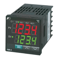
Press for about 5 sec.
Operation/Standby mode
Control output status
Alarm status
PV value
indication
MV value indication lamp is lit
SV value
indication
When the set value
(SV) is displayed at
the lower line, the
SV lamp is lit.
AL2AL1C1 C2 AL3
SEL
PXR
-
4
SV
PV
Manual
AL2AL1C1 C2 AL3
SEL
PXR
-
4
SV
PV
Standby
AL2AL1C1 C2 AL3
SEL
PXR
-
4
SV
PV
Auto
SEL
Press for about 2 sec.
SEL
· If no operation status
continues for 30 seconds,
the screen is restored
to the PV/SV display just
after the power is turned on.
 Loading...


