4
INZ-TN2ZRE-E
Name
①Power switch Used for ON/OFF the analyzer.
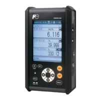
②Display/operation
panel
Liquid crystal display and keys
for setting various functions.
③Flow meter For checking the flow rate of
sampling gas.
④USB connector For connecting to the USB
cable.
⑤Purge gas inlet For connecting to the purge gas
tube.
⑥Sampling gas inlet For connecting to the measuring
gas tube.
⑦Sampling gas
outlet
For connecting to the exhaust
line.
⑧Fuse Fuse inside
⑨Power inlet For connecting to the power
supply line.
⑩External input
connector
For connecting to the output of
externally installed O2 analyzer.
⑪Communication
connector
RS-485 connector for
communication.
⑫Analog output
connector
(D-sub25 pin)
Connector for the analog output
⑬Digital input/output
connector
(D-sub25 pin)
Connector for the digital
input/output
Description Name Description
⑬Digital input/output connector (DIO1 to 3)
(D-sub25 pin)
< Rear panel >
②Display/operation panel
④USB connector
①Power switch
⑧Fuse
⑤Purge gas inlet
⑥Sampling gas inlet (2 systems)
⑦Sampling gas outlet (2 systems)
⑪Communication connector (RS-485)
⑩External input
connector
⑫Analog output connector (A/O)
(D-sub25 pin)
③Flow meter
< Front panel >
⑨Power inlet
A/O
DIO3
DIO2
DIO1
RS485
A/I
MadeinJapan
INFRARED GAS ANALYZER
INLET2 OUTLET2
OUTLET1INLET1
PURGE
POWER INLET
100-240V AC
I
O
ESC
SPANMODE
ENTER
ZERO
E
U
F
S
250VT2AL
FUSE
GAS
ZRE
ANALYZER
SER.NO.
POWER
OUTPUT
MFD
TYPE
100VA
50/60Hz
0-10/25%
AC100V-240V
DC4-20mA
0-200/2000ppm
0-1/10%
0-200/2000ppm
ZREABV41-CGCGJ-MCGC1DE-CFYAA
NO
SO2
CO2
CO
O2
0-200/2000ppm
A9P6146T
2009-12
Fig. 2-2
 Loading...