71
INZ-TN2ZRE-E
NO, SO
2, CO2, CO, CH4 ;
Non-dispersion infrared-ray absorption
method
Single light source and single beams
(single beam system)
O
2
; Fuel cell O2 sensor (built in), zirconia O2
sensor (externally installed TYPE: ZFK7)
or Built in paramagnetic O
2 sensor.
Minimum range Maximum range
NO
SO
2
CO2
CO
O2
External
Zirconia
0 - 200ppm
0 - 5000ppm
0 - 10vol%
0 - 100vol%
0 - 100vol%
0 - 25vol%
0 - 100ppm
0 - 200ppm
0 - 10vol%
0 - 200ppm
CH4 0 - 100vol%0 - 500ppm
0 - 25vol%0 - 5vol%
O2
built in
fuel cell
O2
built in
paramagnetic
0 - 100vol%0 - 5vol%
• Max. 5 components measurement includ-
ing O
2.
• Measuring range ratio max. 1:10
• Measuring ranges are changeable be-
tween the specied minimum and maxi-
mum range
Settable one range or two ranges
• For possible combinations of components
and ranges, refer to Table1.
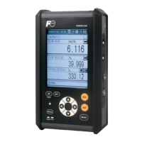
Digital indication in 4 digits
(LCD with CFL back light)
• Instantaneous value of each compo-
nent
• Instantaneous value after O
2 correction
(only in NO, SO
2, CO measurement with
O
2)
• Average value after O
2 correction
(only in NO, SO
2, CO measurement with
O
2)
• O
2 average value
4 to 20mA DC or 0 to 1V DC,
isolated internally from circuit and ground;
12 outputs max.
max. load 550Ω for 4 to 20 mA DC
min. load 100kΩ for 0 to 1V DC
* Refer to Table2 for the channel No. of
displayed values and analog output
signals.
For signal input from externally installed
O
2 sensor.
Signal requirement;
(1) Signal from Fuji’s Zirconia O
2 sensor
(TYPE: ZFK7)
(2) 0 to 1V DC from an O
2 sensor
Input section is not isolated. This
feature is effective when an O
2 sensor
is not built in.
* Externally installed O
2 sensor should
be purchased separately.
1c contact (24V DC/1A, resistive load)
max.15 outputs
Instrument error, calibration error,
range identication, auto calibration
status, High/Low limit alarm contact
output
* All relay contacts are isolated mutually
and from the internal circuit.
Voltage contact (Supply 12 to 24V DC/
15mA max. at ON) max. 9 inputs
Remote range switch, auto calibration
remote start, remote holding, average
value resetting, Isolated from the inter-
nal circuit with photocoupler.
Voltage rating ; 100V to 240V AC
Allowable range ; 85V to 264V AC
Frequency ; 50Hz/60Hz
Power consumption ; 100VA max.
Ambient temperature ;
-
5˚C to 45˚C
(40˚C max. when 2 optical
system at 200V AC power
source)
Ambient humidity ; 90% RH max.,
non-condensing
Altitude ; Up to 2,187yard
[2,000m]
Installation category ; II
Pollution Degree ; 2
Ambient temperature ;
-
20˚C to 60˚C
Ambient humidity ; 100% RH max.,
non-condensing
××
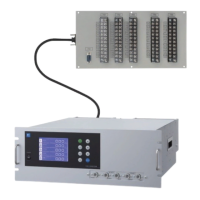
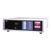
19-inch rack mounting type:
133 × 483 × 418mm
Panel mounting type:
133 × 443 × 418mm
Approx. 8 kg
Front panel; Black (DIC P 1000-F)
Cool gray (PANTON IC-F)
Casing; Cool gray (PANTON IC-F)
Steel casing, for indoor use
Gas inlet/outlet; SUS304
Sample cell; SUS304,chloroprene rub-
ber
Infrared-ray transmitting window; CaF2
O
2 sensor sample cell : SUS316
Internal piping; Toaron, Teon, Viton (In
case of UL model)
Rc1/4 or NPT1/4 internal thread
1L/min ( when required)
2 years
 Loading...