7
INZ-TN2ZRE-E
Observe the following when connecting the gas tube.
●
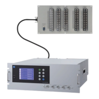
Piping should be connected to the gas inlets and outlets at the rear panel of the analyzer.
●
Use a corrosion resistant tube of Teon, stainless or polyethylene to connect the instrument to
a sampling system. Even if there is a danger of corrosion, refrain from using a tube of rubber
or soft vinyl. The instrument provides inaccurate indication due to gas absorption by piping
materials.
●
Pipe connection port is Rc1/4 female thread (or NPT1/4). Piping should be cut as short as
possible for a quick response. About 4 mm inner diameter is recommended.
●
Entry of dust into the instrument may result in defective operation. Use a clean piping or
coupling.
Sampling gas inlet: Attach the gas tube to introduce gas to be measured such as one that has
completed dehumidication process and standard gases for zero and span
calibration to this inlet.
Gas ow to be introduced should be constant within the range of 0.5 L/min
±0.2 L/min.
Sampling gas outlet: Exhaust measured gas through the outlet. Attach the tube to exhaust mea-
sured gas outdoors or to the atmosphere.
Purge gas inlet: It is used for purging the inside of the total gas analyzer.
Use dry gas N
2
or instrumentation air for purge gas. (Flow rate is 1L/min or
more, and dust or mist is unallowable.)
Purge gas inlet
Sampling gas inlet 1
Sampling gas outlet 1
Sampling gas inlet 2
Sampling gas outlet 2
For special case only
INLET2 OUTLET2
OUTLET1INLET1
A/O
PURGE
DIO3
DIO2
DIO1
RS485
A/I
MadeinJapan
INFRARED GAS ANALYZER
E
U
F
S
250VT2AL
FUSE
PE N L
AC
POWER
V
SOURCE
SER.NO.
POWER
OUTPUT
MFD
TYPE
100VA
50/60Hz
0-10/25%
AC100V-240V
DC4-20mA
0-200/2000ppm
0-1/10%
0-200/2000ppm
ZREABV41-CGCGJ-MCGC1DE-CFYAA
NO
SO2
CO2
CO
O2
0-200/2000ppm
A9P6146T
2009-12
In addition to a sample gas inlet and outlet, there is a purge gas inlet at the rear panel of the
analyzer.
When improper connection is carried out here, combustible gas, poisonous gas, and explo-
sive fumes may be accumulated into the analyzer.
CAUTION
 Loading...