3
WIRING
3-18
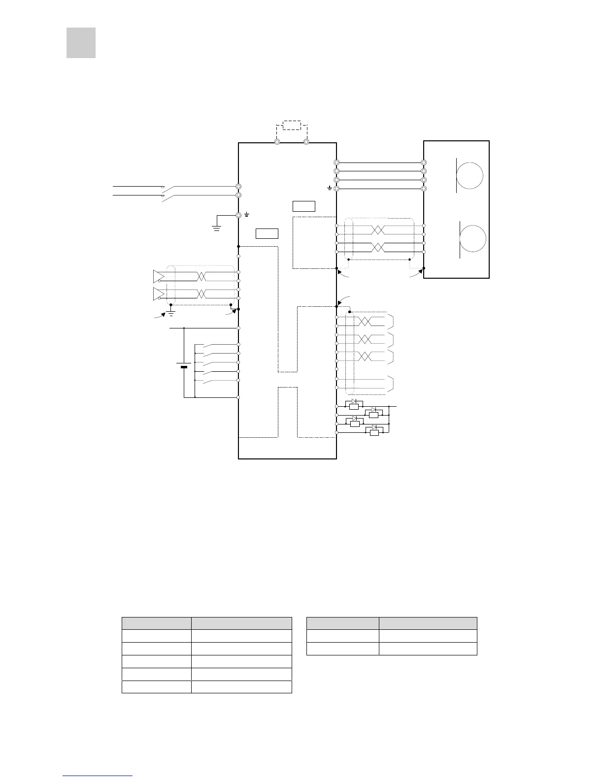
n Single-phase 100 V (without brake)
- The external regenerative resistor is not built in. The external regenerative resistor is prepared as
optional equipment.
- For 500 kVA or larger power supply capacities, connect the power supply coordination reactor.
- Arbitrary signals can be allocated to CONT and OUT terminals.
The factory settings are as follows.
Terminal symbol Factory setting Terminal symbol Factory setting
CONT 1 Operation command [RUN] OUT1 Alarm detection: a-contact
CONT 2 Reset [RST] OUT 2 (Not specified)
CONT 3 (Not specified)
CONT 4 (Not specified)
CONT 5 (Not specified)
U
V
W
1 U
2 V
3 W
4 E
7 CA
8 *CA
21 *CB
20 CB
M
1 P5
2 M5
5 SIG+
6 SIG-
P5 1
M5 2
SIG+ 5
SIG- 6
PG
FZ 25
M5 26
L1
L2
CN1
CN1CN1
CN1
CN2
CN2CN2
CN2
1 P24
2 CONT1
5 CONT4
3 CONT2
6 CONT5
14 M24
4 CONT3
P24
P24P24
P24
OUT1 15
OUT2 16
RDY 17
PSET 18
P24
P24P24
P24
DB
19 PPI
P
DC24V
M5 13
FFA 9
FFB 11
*FFB 12
FFZ 23
*FFZ 24
*FFA 10
*1
*2
*1 *1
*1
Servo amplifier
Commercial power supply
Single-phase 100 V
External regenerative resistor
(option)
Servomotor
(Without brake)
Phase-A pulse output (differential)
Phase-B pulse output (differential)
Phase-Z pulse output (differential)
Phase-Z pulse output (open collector)
Power input for pulse string open-collector input
Pulse train input
(differential)
*1: Connect the shielding wires to the connector shell of CN1 and CN2. The connector shell is connected with the grounding
terminal.
*2: Ground the shielding wire at both ends. (Connect it to the connector shell on the amplifier side, and connect it to the FG
(ground) terminal on the pulse generator side.



 To Next Page