TEST OPERATION
4
4-3
4-2) First stage
Connect the servo amplifier and servomotor to perform test operation. Refer to Chapter 3 for the wiring
method.
Do not connect the servomotor to the mechanical system when performing test operation.
Check the following items in the first stage.
<Items to be checked>
1. Check the power supply wiring of the servo amplifier (L1, L2 and L3).
2. Check the servomotor power cables (U, V and W) and encoder cable.
3. Check if the servo amplifier and servomotor function correctly.
4. Check parameter #4 (switching direction of rotation).
n Test operation procedure
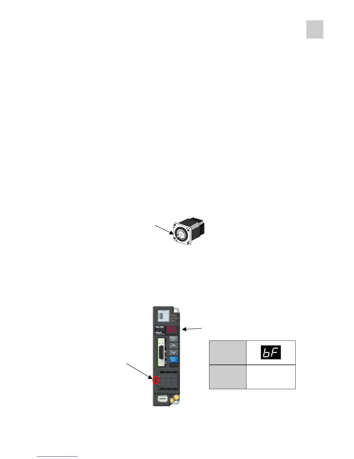
(1) Fix the servomotor so that it will not fall.
(2) Referring to Chapter 3, connect cables to the servo amplifier and the servomotor.
(3) Turn the power on.
Check the charge LED (i) and keypad panel indication (ii).
Fix securely.
Mount nothing on the motor shaft.
i) Check the charge LED.
Red LED lights up in the normal
state.
ii) Check the touch panel indication.
When faulty
A value between 1
and 19 blinks.
(Alarm detection)
When correct
* If an alarm is detected, turn the power off, check wiring, and refer to Chapter 9.



 To Next Page