5
PARAMETERS
5-16
5-4) System settings
System setting parameters are described in the order of the parameter number.
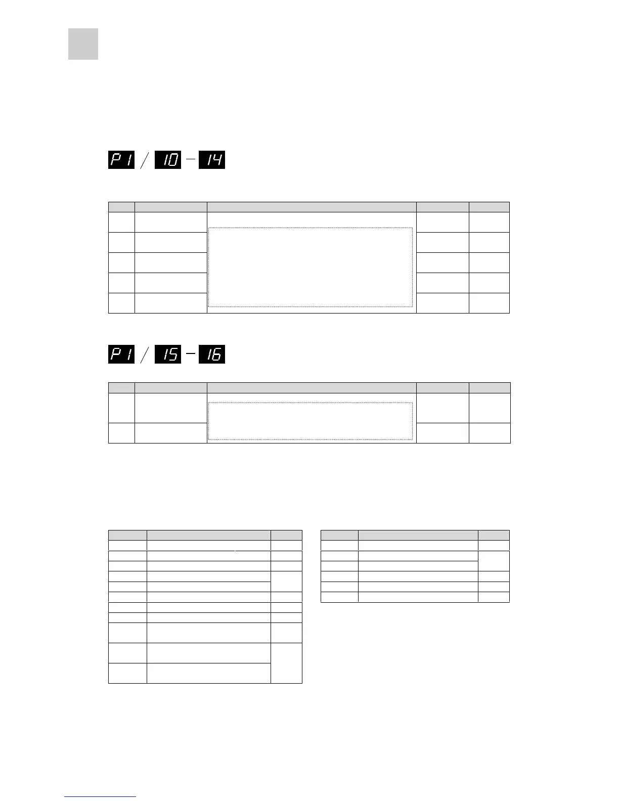
System setting parameters #10 through #14
No. Name Setting range Initial value Change
10
CONT 1 signal
allocation
1 [RUN] Power
11
CONT 2 signal
allocation
2 [RST] Power
12
CONT 3 signal
allocation
0 Power
13
CONT 4 signal
allocation
0 Power
14
CONT 5 signal
allocation
0 to 10 (in 1 increments)
0 Power
System setting parameters #15 and #16
No. Name Setting range Initial value Change
15
OUT 1 signal
allocation
1 Alarm
detect:
a-contact
Power
16
OUT 2 signal
allocation
0 to 5 (in 1 increments)
0 Power
The following functions can be assigned to sequence input/output terminals.
n CONT signal allocation number n OUT signal allocation number
Setting Name Page Setting Name Page
0 Not specified - 0 Not specified -
1 Operation command [RUN] 5-18 1 Alarm detection: a-contact
2 Reset [RST] 5-19 2 Alarm detection: b-contact
5-28
3 + overtravel [+OT] 3 Dynamic brake 5-29
4 - overtravel [-OT]
5-20
4 Overtravel detection 5-20
5 Forced stop [EMG] 5-22 5 Forced stop detection 5-22
6 P-action 5-24
7 Deviation clearance 5-25
8
External regenerative resistor
overheat
5-26
9
Anti-resonance frequency
selection 0
10
Anti-resonance frequency
selection 1
5-27
0: Not specified 1: Operation command [RUN]
2: Reset [RST] 3: + overtravel
4: - overtravel 5: Emergency stop [EMG]
6: P-action 7: Deviation clearance
8: External regenerative 9: Anti-resonance frequency
resistor overheat selection 0
10: Anti-resonance
frequency selection 1
0: Not specified 1: Alarm detection: a-contact
2: Alarm detection: 3: Dynamic brake
b-contact
4: Overtravel detection 5: Forced sto



 To Next Page