PARAMETERS
5
5-17
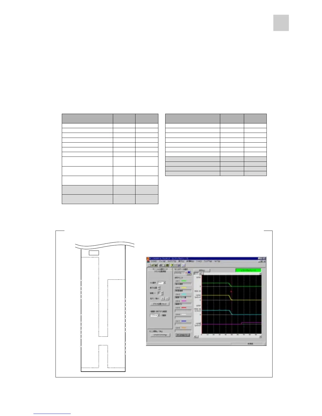
n Each sequence input/output signal can be monitored in the trace screen of the PC loader.
The ready [RDY] and positioning end [PSET] signals among sequence output signals are fixed at the
OUT terminals.
O: Terminal allocation and waveform trace are possible.
Sequence input signal
CONT
allocation
PC loader Sequence output signal
OUT
allocation
PC loader
Operation command [RUN]
¡¡
Alarm detection: a-contact
¡¡
Reset [RST]
¡¡
Alarm detection: b-contact
¡¡
+ overtravel [+OT]
¡¡
Dynamic brake
¡¡
- overtravel [-OT] ¡¡Overtravel detection ¡¡
Forced stop [EMG] ¡¡Forced stop detection ¡¡
P-action
¡¡
Ready [RDY] x (Fixed)
¡
Deviation clearance
¡¡
Positioning end [PSET] x (Fixed)
¡
Zero deviation*
H
¡
External regenerative
resistor overheat
¡¡
Zero speed*
H
¡
Torque limit detection*
H
¡
Anti-resonance frequency
selection 0
¡¡
CPU ready*
H
¡
Anti-resonance frequency
selection 1
¡¡
Manual forward rotation
[FWD]*
H
¡
(For test op.)
Manual reverse rotation
[REV]*
H
¡
(For test op.)
* Only waveform at the PC loader can be traced.
Terminals cannot be allocated.
7 CA
8 *CA
CN1
CN1CN1
CN1
19 PPI
21 *CB
20 CB
FZ 25
M5 26
FFA 9
FFB 11
*FFB 12
FFZ 23
*FFZ 24
*FFA 10
1 P24
2 CONT1
5 CONT4
3 CONT2
6 CONT5
14 M24
4 CONT3
OUT1 15
OUT2 16
RDY 17
PSET 18
Servo amplifier
M5 13
Terminal allocation of connector 1 (CN1) of servo amplifier and trace screen of PC loader



 To Next Page