WIRING
3
3-31
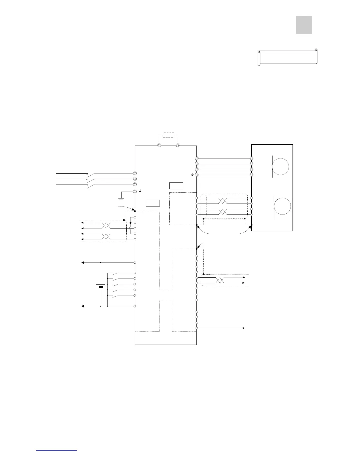
n Position control unit (C200HW-NC113 type)
<Setting example>
l C200HW-NC113 position control unit
The pulse output mode is used to output CW and CCW pulses.
Servo side
U
V
W
1 U
2 V
3 W
4 E
7 CA
8 *CA
21 *CB
20 CB
M
1 P5
2 M5
5 SIG+
6 SIG-
P5 1
M5 2
SIG+ 5
SIG- 6
PG
FZ 25
M5 26
L1
L2
L3
CN1
CN1CN1
CN1
CN2
CN2CN2
CN2
1 P24
2 CONT1
5 CONT4
3 CONT2
6 CONT5
14 M24
4 CONT3
M24
⑨
DB
19 PPI
P
⑤
⑥
*1
OUT1 15
OUT2 16
RDY 17
PSET 18
⑦
M5 13
FFA 9
FFB 11
*FFB 12
FFZ 23
*FFZ 24
*FFA 10
①
②
③
④
*1
*1
*1
P24
⑧
DC24V
Servo amplifier
Commercial power
supply 3-phase 200V
External regenerative
resistor (Option)
Servomotor
(Without brake)
*1: Connect the shielding wires to the connector shell of CN1 and CN2. The connector shell is connected with the grounding terminal.
*2: Ground the shielding wire at both ends. (Connect it to the connector shell on the amplifier side, and connect it to the FG (ground) termin
 Loading...