Getting Started
Chapter 8 Appendix
© Fujitsu Microelectronics Europe GmbH - 41 - MCU-AN-391005-E-V17
8 Appendix
8.1 Figures
Figure 1: Installing the crystal for the main clock..................................................................... 9
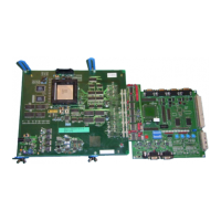
Figure 2: Connections of the Emulator MB2198-01............................................................... 10
Figure 3: Mounting the Evaluation MCU................................................................................ 11
Figure 4: Connected Adapter Board and Evaluation Board................................................... 12
Figure 5: The Correct Polarisation of the 9 V DC Power Supply. .......................................... 12
Figure 6: Cabling the Adapter Board and Evaluation Board.................................................. 13
Figure 7: Connected Adapter Board, Probe Cable and Evaluation Board............................. 13
Figure 5: The Correct Polarisation of the 9 V DC Power Supply. .......................................... 14
Figure 7: Cabling the Adapter Board, Probe Cable and Evaluation Board............................ 14
Figure 8: Default Jumper Settings of the Adapter Board ....................................................... 21
Figure 9: Default Jumper Settings of the Evaluation Board SK-91460-MAIN........................ 23
Figure 10: Default Jumper Settings of the Evaluation Board SK-91F467D-208PFV............. 24
Figure 10: Default Jumper Settings of the Probe Cable PB-91467D-208PFV....................... 25
Figure 10: Default Jumper Settings of the Probe Cable PB-91467D-LS-208PFV ................. 26
Figure 11: Copy the Template Project ................................................................................... 27
Figure 12: Open a Workspace............................................................................................... 28
Figure 13: The MAIN.C Code of the Template ...................................................................... 29
Figure 14: Debugging Mode after a successful Connection .................................................. 31
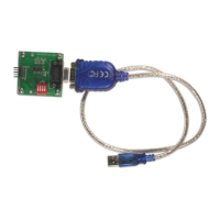
Figure 15: Installing the USB-driver I..................................................................................... 33
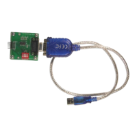
Figure 16: Installing the USB-driver II.................................................................................... 33
Figure 17: Choose the search options................................................................................... 34
Figure 18: Close the hardware wizard ................................................................................... 34
Figure 19: Changing the IP-Address...................................................................................... 35
Figure 20: Add a Service ....................................................................................................... 36
Figure 21: Add a Host............................................................................................................ 37
Figure 22: Edit the File Imhosts.asm ..................................................................................... 38
Figure 23: Testing the IP-Connection to the Emulator I......................................................... 39
Figure 24: Testing the IP-Connection to the Emulator II........................................................ 39
Figure 25: Changing the IP-Address of the Host in the Softune Workbench......................... 40
 Loading...