Do you have a question about the Fujitsu WATERSTAGE 112 and is the answer not in the manual?
Precautions and overview of electrical connections for the heat pump system.
Important safety and installation precautions for electrical connections.
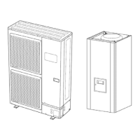
Pre-startup checks for the outdoor unit, hydraulic unit, and systems.
List of hydraulic unit faults with designation, location, reset type, and operation.
Procedures for clearing common outdoor unit faults with error codes.
Common failures and troubleshooting for hydraulic, electric, and refrigeration systems.
Troubleshooting steps when the outdoor unit fails to defrost.
General troubleshooting steps for when the heat pump is not operating.
Detailed explanation of adjustable functions and parameters.
Explanation of heating curve settings and their impact on flow temperature.
Functions for displaying and managing errors.
Functions for periodic maintenance and special operating modes.
Annual maintenance tasks for the hydraulic circuit.
Annual maintenance tasks for the outdoor unit.
Wiring diagram for the hydraulic unit's components and connections.
Wiring diagram for the outdoor unit's components and PCBs.
Step-by-step instructions for removing the main PCB.
Instructions for removing the INVERTER, PFC, FILTER, and CAPACITOR PCBs.
Step-by-step instructions for removing the fan motor.
Instructions for removing thermistors.
Instructions for removing solenoid coils.
Instructions for removing EEV coils.
Step-by-step instructions for removing the pressure sensor.
Precautions and procedure for removing the compressor.
Important precautions for handling refrigerant cycle parts during work.
Step-by-step guide for initial setup and startup of the Hydraulic Unit.
Comprehensive checklist for verifying installation and startup readiness.
| Category | Air Conditioner |
|---|---|
| Cooling Capacity | 11.2 kW |
| Heating Capacity | 12.5 kW |
| Outdoor Unit Weight | 65 kg |
| Sound Pressure Level (Outdoor) | 52 dB(A) |