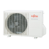
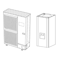
Heat Pump, Split System, Single Service, 3 phase
Maintenance Document 1394-1 23
4 Faults
4.1 Fault List
4.1.1 Hydraulic Unit Fault
Faults which occur on the Hydraulic Unit are shown
by the symbol
. Press the info key for details on the
cause of the fault. The following information is
displayed:
• Description of the error
• Location of the error (sensor or contact)
• Reset. Depending on its type, the fault can be
manually or automatically deleted:
Manual delete: the text displayed when pressing
the info key shows "reset ?". Press OK once, the
yes flashes; press again to confirm deletion of the
fault.
Faults whose deletion is automatic are
automatically reset.
• Heat pump op: shows whether or not the heat pump
operates despite the fault.
Reset
No.: Designation of error
Location
(connection)
Manual Auto
HP op
10: Outdoor sensor B9 No No Yes
33: Heat pump flow temp sensor error B21 No No Yes
44: Heat pump return temp sensor error B71 No No per diagram
50: DHW temp sensor B3 No No Yes
60: Room sensor 1 No No Yes
65: Room sensor 2 No No Yes
105: Maintenance message No No Yes
121: HC1 flow temp not reached No No Yes
122: HC2 flow temp not reached No No Yes
127: Legionella protection temp not reached No No Yes
369: External fault (safety component)
No
370: Outdoor unit fault* Yes Yes No
* A fault in the outdoor unit is indicated by LED located on the Hydraulic Unit interface board.
LED display
LED 2 (green) LED 1(red)
Fault description
1 Flash 1 Flash Communication error between Hydraulic Unit and Outdoor unit.
4 Flashes 1 Flash Heat pump capacity signal error (Open or short).
4 Flashes 2 Flashes Hydraulic Unit heat-exchange thermistor Error.
6 Flashes 3 Flashes Inverter error.
6 Flashes 4 Flashes Active filter error.
PFC error.
7 Flashes 1 Flash Discharge thermistor error.
7 Flashes 2 Flashes Compressor thermistor error.
7 Flashes 3 Flashes Heat-exchange thermistor (outlet) error.
Heat-exchange thermistor (intermediate) error.
7 Flashes 4 Flashes Outdoor thermistor error.
7 Flashes 7 Flashes Heat sink thermistor (inverter) error.
Heat sink thermistor (P.F.C.) error.
7 Flashes 8 Flashes Expansion valve thermistor error.
8 Flashes 4 Flashes Current sensor error.
8 Flashes 6 Flashes Pressure sensor error.
Pressure switch error.
9 Flashes 4 Flashes Current trip.
9 Flashes 5 Flashes Detection of compressor position error.
Compressor start up error.
9 Flashes 7 Flashes Outdoor unit fan motor error.
10 Flashes 1 Flash Discharge temperature protection.
10 Flashes 3 Flashes Compressor temperature protection.
10 Flashes 5 Flashes Low pressure abnormal.
Continuous flashing (1 sec ON / 1 sec OFF) Pump down operation.
 Loading...