Heat Pump, Split System, Single Service, 3 phase
Maintenance Document 1394-1 135
12.4 Startup Data Sheet
Site:
Installer:
Serial no.:
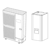
Serial no.: Outdoor unit
Model:
Hydraulic Unit
Model:
Refrigerant type: Refrigerant charge: kg
Checks Operating voltage and current on Outdoor Unit
Compliance with positioning distances L1/N, L2/N, L3/N : V
Condensate evacuation correct L1/E, L2/E, L3/E : V
Electric connections/connections tightness N/E: V
No GAS leaks (Unit ID No.: ______) Icomp: A
Installation of refrigeration connection correct (length: m)
Reading in HEATING operating mode
Compressor discharge temperature: ______°C
Liquid line temp °C
Condensation temp HP = ______bars °C Sub-Cooling =______°C
Tank water output temp °C ▲T condensation = ______°C
Tank water input temp °C ▲T secondary = ______°C
Evaporation temp LP = ______ bars °C
Suction temp °C Overheating =______°C
Heat exchanger air input temp °C ▲T Evaporation = ______°C
Heat exchanger air output temp °C ▲T Heat exchanger = ______°C
Hydraulic system on Hydraulic Unit:
}
}
}
}
}
}
Low temp heating floor Pump brand: ___________ Type:__________
LT Radiators
Secondary system:
Fan coils
Pump brand: ___________ Type:__________
Domestic hot water: tank type =_______
}
Pump brand: ___________ Type:__________
Estimated water volume of secondary system: ______ L
Options & Accessories:
Power supply for connected electric auxiliary
Operation in cooling mode possible Room thermostat C 55
Location of room sensor correct
Remote control C75
Cooling kit Boiler kit: _____________
DHW kit
2-zone kit
Details:
Control Settings:
Configuration type:
Essential settings:
Observations
Startup Date Name and signature of person in attendance Name and signature of Technician
 Loading...