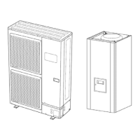
Heat Pump, Split System, Single Service, 3 phase
128 Maintenance Document 1394-1
2284Z33a
2284Z34a
2284Z35a
Connection:
The room thermostat must be connected to one of
the terminals b (CL+, CL-) of the heat pump controller
board. To do this, you can use a 0.5mm² cable of the
two-pair telephone cable type.
If the cable is shielded, the shielding can be
connected to the controller CL- terminal. It may under
no circumstances be connected on both sides, i.e.
controller side and room unit side.
If the installation is equipped with 2 room
thermostats, the second thermostat must be
connected to the second terminal block b.
Configuration:
Gain access to the settings by continuously pressing the "Heating mode" key
fs = 1 (factory setting) Æ The room unit is addressed as ZONE 1
fs = 2 Æ The room unit is addressed as ZONE 2
fs = 3 Æ The room unit is addressed as ZONE 3 (factory setting)
P1 = 1 (factory setting) Automatic save:
Correction of the setpoint using the knob is accepted without special confirmation (timeout) or by pressing the
operating mode key.
P1 = 2 Confirm save
Correction of the setpoint with the knob is accepted only after pressing the operating mode key.
1 CL+
2 CL-
1
34
562
2284 Z40
User interface
 Loading...