SP - 2 E3503S02C
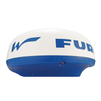
2.3. MODEL1943C:
2.3.1. Radiator Slotted waveguide array
2.3.2. Polarization Horizontal
2.3.3. Antenna Rotation 24 or 48 rpm nominal
High brilliance monitor: 24 rpm nominal only
2.3.4. Radiator Length 120 cm (XN12)
2.3.5. Horizontal Beamwidth 1.9°
2.3.6. Vertical Beamwidth 22°
2.3.7. Sidelobe Attenuation -24 dB or less (within ±20° of main-lobe)
-30 dB or less (±20° of main-lobe or more)
3. TRANSCEIVER MODULE
3.1. Frequency and Modulation 9410 MHz ±30MHz (X band), P0N
3.2. Peak Output Power M1833C/1933C: 4 kW nominal,
M1943C: 6 kW nominal
3.3. Modulator FET Switching Method
3.4. Intermediate Frequency 60 MHz
3.5. Tuning Automatic or manual
3.6. Receiver Front End MIC (Microwave IC)
3.7. Bandwidth Tx pulselength 0.08 µs and 0.3 µs: 25 MHz
Tx pulselength 0.8 µs: 3 MHz
3.8. Duplexer Circulator with diode limiter
3.9. Warming up 90 sec. approx.
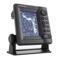
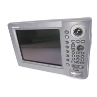
4. DISPLAY UNIT
4.1. Display 10.4-inch rectangular TFT color LCD
640(H) x 480(V) dots, Effective radar display dia.: 152 mm
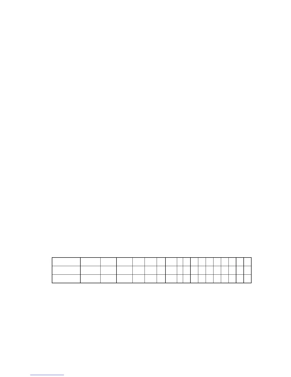
4.2. Range, Range Ring Interval (RI), Number of Rings
Range (nm) 0.125 0.25 0.5 0.75 1 1.5 2 3 4 6 8 12 16 24 36 48 64
RI (nm) 0.0625 0.125 0.125 0.25 0.25 0.5 0.5 1 1 2 2 3 4 6 12 12 16
Rings 2 2 4 3 4 3 4 3 4 3 4 4 4 4 3 4 4
Maximum range: M1833C: 36nm, M1933C: 48nm, M1943C: 64nm
4.3. Markers Heading Line, Bearing Scale, Range Rings,
Variable Range Marker (VRM), Electronic Bearing Line (EBL),
Alarm Zone, Waypoint Mark (navigation input required)
4.4. Alphanumeric Indications Range, Range Ring Interval, Interference Rejection (IR),
Variable Range Marker (VRM), Electronic Bearing Line (EBL),
Stand-by (ST-BY), Echo Averaging (EAV), TX Pulse width
 Loading...