1. INSTALLATION
at the back of this manual.
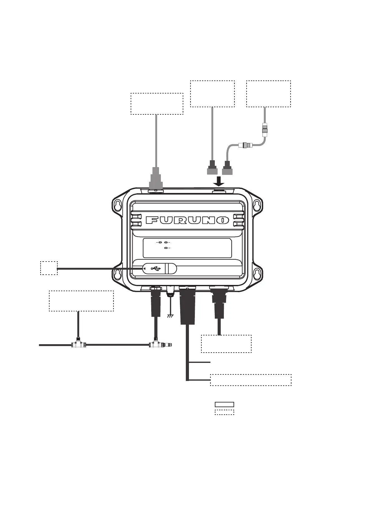
POWER
ERROR
RX
VHF Antenna
CX4-3/FEC
5D-2V
PC
USB Cable, Max 2 m
Ground
IV-1.25sq
NPD-MM1MF
1000G02M, 2 m
T-connector
NMEA2000 Sensor**
or External Display
**: GP-1871F/1971F, TZT9/14/BB, TZTL12F/15F,
TZT2BB, TZT12F/16F/19F, FAR-1416/1426,
FI-70, etc.
: Standard supply
: Optional or local supply
NAV Equipment
or Sensor
MJ-A6SPF0003, Max. 15 m
Ship’s Mains 12-24 VDC
NAV Equipment or Sensor
VHF ANT GPS ANT
NMEA2000
PWR/NMEA1
NMEA2
Option*: 8D-FB-CV,
30/40/50 m
Local supply*:
RG-10/UY, 20 m
or
TNC-PS/PS-3D-
L15M-R, 15 m
*: NJ-TP-3DXV
(1 m) is required.
Antenna Unit
GPA-017S
or
Antenna Unit
GPA-017 or
GPA-C01
TNC-P-3,
10 m
To connect a monitor that supports NMEA2000
format version 1, set [NMEA2000] - [Format] to
[NMEA2000 V1] (see section 3.1). To connect
multiple monitors where one supports version 1
and the other supports version 2, connect one
of the monitors to the NMEA0183 port.
(Local supply)
(Option)