7.4 Control Unit
7-72
The figure below is the block diagram of connection of RCU-013 and RCU-014. See
page.4-58 for information of System Fail.
Fig. 7.4.2 Block diagram of connection
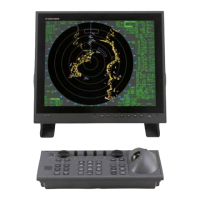
The second control unit to be connected is RCU-016.
If RCU-014 or RCU-015 is connected as the second unit, the following operations are
disabled form the second unit.
- The power cannot be turned on and off
- A key beep does not sound.
- Key lighting cannot be used.
For these reasons, use RCU-016 to be connected as the second control unit.
TX/RX 0 TX/RX 1
TD UP H/CKEY TXD H/C
RD UP H/C
TD DN H/C
RD DN H/CKEY RXD H/C
U21
MAIN CPU
U8
CPU
SYS FAIL N
SYS FAIL H
SYS FAIL H
SYS ACK H
SYS ACK N
RADAR OK
SYS FAIL C
SYS FAIL H
SYS FAIL C
SYS FAIL C
1
23
4
1
1
2
2
1
2
3
4
11
12
1
to
8
1, 2
3, 4
J507
J612
J622
J501
PROCESSOR
J502
REMOTE
J506
J602
GND
GND
GND
GND
GND
PWR SW
U14
U12
(PS7241 1B)
SN751178NS
SN751178NS
RS422 I/F
SN751178NS
5
6, 8
7
9
10
1, 2
3, 4
5
6, 8
7
9
10
1, 2
3, 4
5
6, 8
7
9
9
10
12V IN12V
12V IN
POWER SW
PWR
p.c.b
S36
(DIP SW)
BZ
U9
SOUND
U6
(RS422 I/F)
U6
(RS422 I/F)
KEY &
ILLUMI
Rotary
Encoder
RCU-014
RPU-013
RCU-016
EXT ALARM ACK N
PROCESSOR
SYSTEM FAIL
EMRI
REMOTE
KEY
KEY
EXT ALARM
ALARM 1 ALARM 2
ALARM 3 OPERATOR FITNESS
TERMINAL
p.c.b
SPU
p.c.b
 Loading...