7.5 Monitor Unit
7-76
7.5.3 List of monitor units
The table below shows color LCD monitors connectable with FAR-2xx7 series.
Table 7.5.2 Connection of LCD monitor
Model
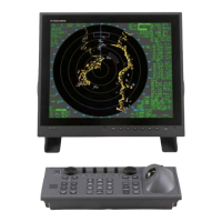
MU-201CR
(Standard)
MU-231CR
(Standard)
MU-120C MC-155C MU-151C MU-201C
Connection
with FAR
Yes Yes Electrically connectable
No Yes
Picture size
(inch)
20.1 23.1 12.1 15
15 20.1
Monitor
resolution
1024 x 1280
(SGXA)
1200 x 1600
(UXGA)
800 x 600
(SVGA)
1024 x 768
(XGA)
1024 x 768
(XGA)
1024 x 1280
(SXGA)
Input
connector
DVI-D
- DVI-D
- Mini D-SUB15 pin
RGB analog
- RCA
NTSC/PAL
RGB analog
Mini D-SUB
15 pin
- RGB analog
Mini D-SUB
15 pin
- DVI-D
Power
supply
100-240 VAC
/24 V
12-24VDC
100-240
VA C
/24 VDC
100-240 VAC
SPU board
S1-#1/2
OFF/OFF ON/OFF OFF/ON
OFF/ON
Remaks
Note-1, Note-2
Note-3, Note-4
Note-1
Note-2
Note-3
Note-1
Set S1-#1/2 of the SPU board to OFF/ON. In this setting;
- Brilliance control signals included in DVI signals are not outputted.
- The [BRILL] icon bar is not displayed at the lower left of the screen.
Note-2
When connection with FAR is made by RGB analog signals, the connection should be
made by way of DVI I/F and RGB BUFF boards offered as option. See the
Installation Manual of FAR radar for the method of connection.
Note-3
For connection with the DVI-D connector, make connection directly. RCA signals are
not supported.
Note-4
Due to difference in monitor resolution, signals are omitted and this makes characters
illegible
 Loading...