3-1
3.1 General
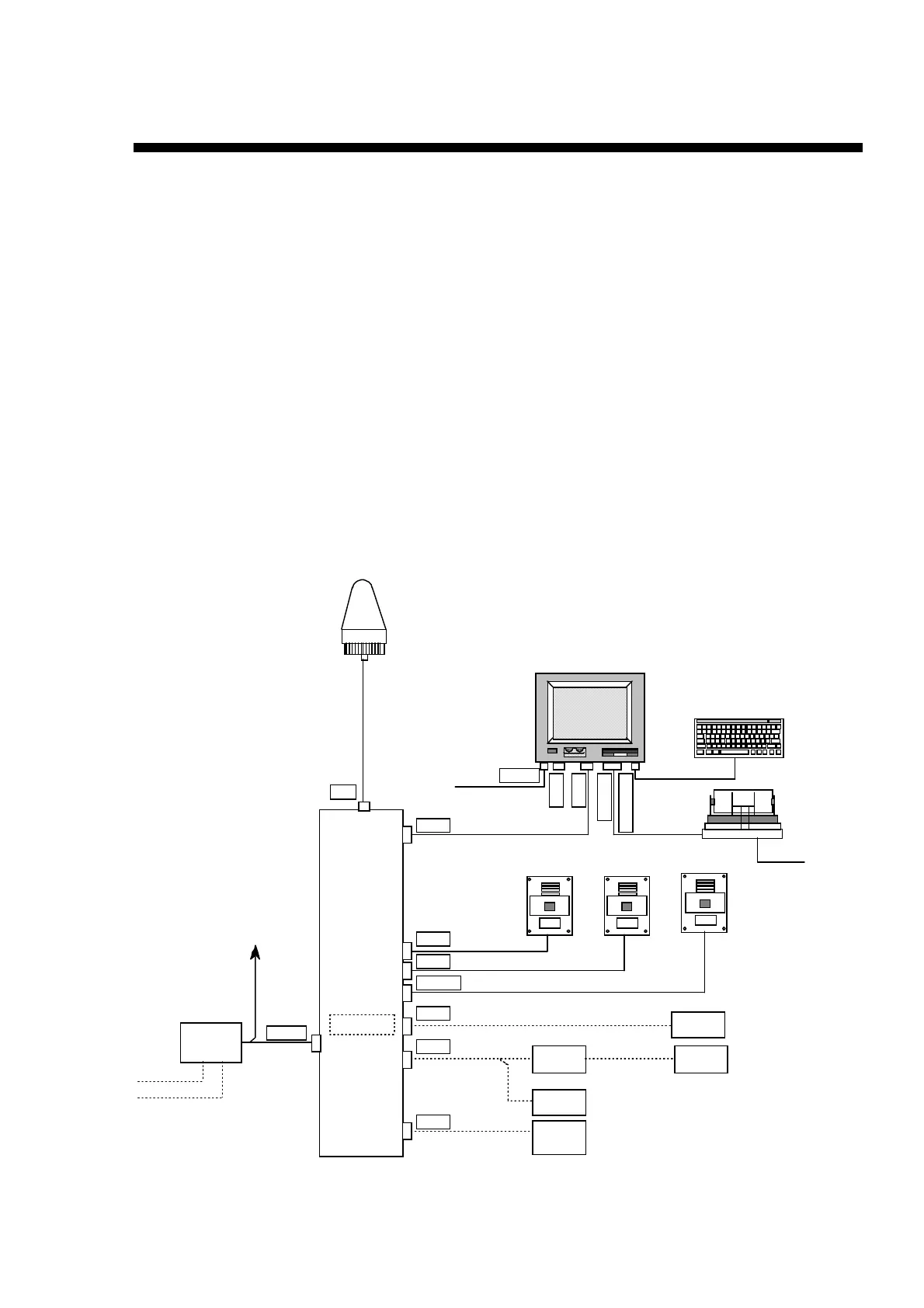
Interconnection diagram of FELCOM 12 is shown below.
Communication Unit: IC-212 and Antenna Unit: IC-112 are connected with a coaxial
cable, through which receiving signals of 1530.0 to 1545.0 MHz, transmitting signals
of 1626.5 to 1646.5 MHz, and power supplies from IC-212 to IC-112 ( +29 V for the
transmitting and +18 V for the receiving ) are sent.
The signal transmission loss of the coaxial cable in 1.6 GHz band is estimated to be 3
to 13 dB, so the cable to be used should be selected from specified cables in
accordance with the cable length between the two units.
IC-212 consists of REG, CPU, RF CON, and TX boards. IC-112 consists of an
antenna board: ANT, a diplexer: DIPLEXER, and a helical antenna.
GPS position signals can be received with an optional GPS receiver board (GN-74)
installed in IC-212. The GPS signals are not only utilized for FELCOM 12, but
outputted therefrom in NMEA-0183 format. Outputted are GLL, GGA, VTG, RMC,
and ZDA.
FURUNO
KEYBOARD
COM 1
PRINTER
COM 2
24V DC
IB-581
PP-510
KEYBOARD
IC-112
ANT
DTE 1
DTE 2
DMC 1
DMC 2
BUZZER
DATA
NMEA
24V DC
NPNP
NP
IC-303IC-302IC-302
Navaid
I/F BOX
(OP16-14)
EGC printer
(PP-505)
IB-581
AC/DC power
supply
(PR-300)
IC-212
DC24V
DC24V
AC100/200
BATT 24V
DC24V
*
*
*
*
*
•
5D-FB-CV : 30m
•
8D-FB-CV : 50m
•
12D-SFA-CV : 100m
•
IC-302 : Distress Alert Unit
•
IC-303 : Received Call Unit
NMEA-0183
GPS received
board
*
IB-581
or PC
*: optional
Figure 3-1 Configuration of FELCOM12
Chapter 3 Block Description
 Loading...