3-4
3.3 Functions of Each Board
Unit PCB Name PCB Type Function Remarks
Helical ant. -
Consists of two pairs of antenna elements different in length,
generating a right circular polarization wave.
DIPLEXER -
An isolation circuit between transmitting and receiving
signals. Its Isolation is:
•
TX
→
RX: more than 40 dB,
•
RX
→
TX: more than 40 dB.
The loss in the pass band is less than 1.0 dB.
Do not
adjust any
screws.
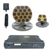
Antenna
Unit
(IC-112)
ANT 16P0146
Comprises L-band amplifier circuits for signal transmission
(1626.5 - 1646.5 MHz) and reception (1530.0 - 1545.0 MHz).
The operational input voltage is +29 V for transmission and
+18 V for reception. The amplifier gain is:
•
-5 dBm (input)
→
+43 dBm (output) for transmission, and
•
+33
to
38 dB for reception.
TX 16P0157
Consists of a switching circuit between transmitting and
receiving signals, and a transmitting amplifier circuit (L
band).
•
Transmitting gain: +28 dB
•
Receiving gain: -2 dB
RF CON 16P0147
Comprises a reference oscillator: VCXO (15.6 MHz),
transmitting/receiving synthesizer circuits, BPSK modulator,
and amplifier and frequency converter circuits for receiving
signals.
•
Receiving IF signal: 50 kHz, supplied to CPU board.
•
Transmitting modulation signal: S-DATA is fed from CPU
board.
CPU 16P0148
Consists of BPSK demodulation circuit, control circuit,
transmitting/receiving signal processing circuits (by CPU),
and input/output interfaces.
EE-PROM
(U11)
Having
FID/RID
REG 16P0149
Includes a switching regulator power supply circuit with a 24-
V input which supplies +5 V, +12 V, and a power switching
circuit; between +29 V in TX and +18 V in RX. ANT VOL
detection circuit to detect short-circuits in ANT coaxial cable
and ANT CUR detection circuit to detect transmitting power
are also included.
Fan is on
during TX.
Communi-
cation Unit
(IC-112)
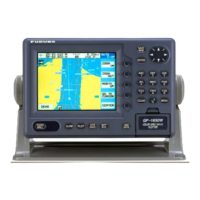
GPS GN-74 GPS receiver circuit Optional
CPU CARD AR-B1374 Controls printer, keyboard, main unit, and memory.
VGA CARD AR-B1041 Controls LCD.
FDD
FD-235HF-
7529
Controls floppy disk drive.
T. BOAED 16P0141
Power supply circuit for VGA CARD - LCD relay and LCD
illumination.
POWER
ACE-870C-
B1
Generates ±12 and ±5 V by a switching power circuit from
+24-V input.
LCD LCD
Terminal
Unit
(IB-581)
FIL 16P0144 A power line filter
Keyboard
BTC-5100C
PS/2
A keyboard
Printer PP-510 Centronics specifications Optional
Disterss
Alert Unit
IB-302 16P0150
Consists of a button-ON detector of distress alert unit, a lamp,
and a buzzer.
Two units
supplied
Received
Call Unit
IB-303 16P0150
Consists of a reception buzzer, a buzzer-OFF detector, and an
indicator lamp.
I/F BOX OP16-14
A circuit for converting RS-232C to current loop for the
purpose of extending PP-505 cable
Optional
EGC
Printer
PP-505 A printer exclusively used for EGC Optional
AC/DC
PWR Unit
PR-300 An AC/DC automatic switching power supply Optional
 Loading...