5-4
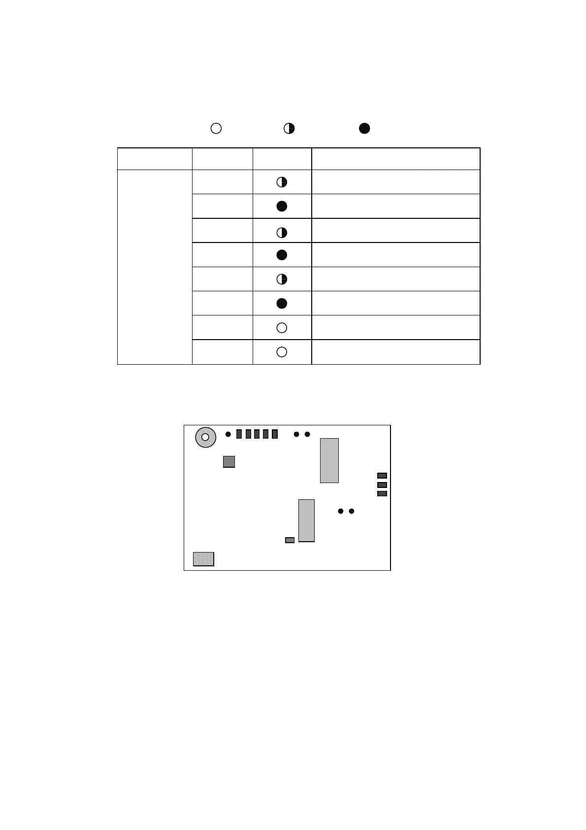
5.2 LED Check
The table below shows LED state on the PCBs.
: on : blinking : of
CPU Board
(16P0147)
Board LED No. State Function
CR 2
CR 9
CR 8
CR 7
CR 6
CR 5
CR 4
CR 3
Blinks when CPU2 operates correctly.
Lights when CPU2 error is detected.
Blinks when unique words are detected
(on for 8.14 sec, off for 0.5 sec)
Lights when CPU1 error is detected.
Blinks when CPU1 operates correctly.
Lights during carrier signal acquisition and
goes off when signal is aquired. (FFT)
Lights when signal is acquired. (FFT)
Lights during set-up process at power-up.
(GRN)
(RED)
(GRN)
(RED)
(GRN)
(RED)
(GRN)
(ORG)
FFT: Font Fourier Transform
CR 7
CR 8
CR 9
CR 2
CR 3
CR 4
CR 5
CR 6
TP4 TP5
S1
U39 : ROM
U44 : DEMOD
ROM
BATT
BUZZER
U11 : EE-PROM
TP1
TP3 TP2
Figure 5-1 Location of LED and Test Point on CPU Board
 Loading...