5-5
5.3 Check Points
CPU Board
(16P0148)
Board name TP No. Status
TP 1
TP 3
TP2
TP 1
TP 5
TP 4
TP 3
TP 2
TP 4
RF CON Board
(16P0147)
Signal
GND
GND
TX CLK
DEMOD OUT
50kHz IF
50kHz IF
AGC Level
GND
Rx waveform, during synchronization
Rx waveform
Rx waveform output
Rx IF AGC Level on status monitor
display; 130=5V, 100=4V, 80=3V
Remarks
5Vp-p
(1200Hz)
4Vp-p
DC5V ~ 6V
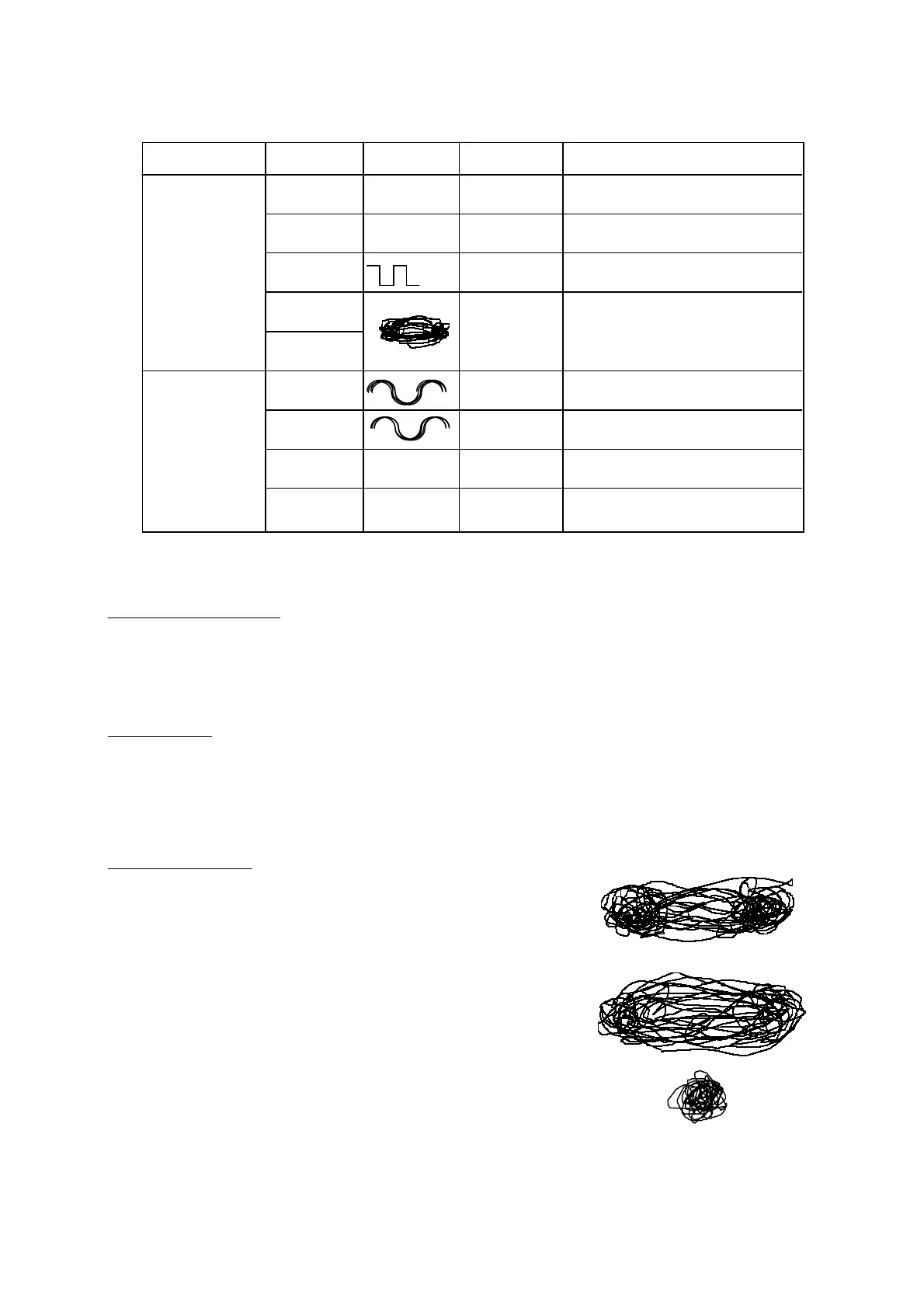
Measurement of DEMOD output
Oscilloscope Settings
•
MODE : X-Y CONV
•
VOLTS/DIV : 0.5/DIV
•
TIM/DIV : X-Y
Connections
CH1 ------ TP4 or TP5
CH2 ------ TP5 or TP4
GND ----- TP1 or TP2
Lissajous Figures
•
When C/N in status monitor display is 40dB
(synchronized); Two poles can be recognized.
•
When C/N in status monitor display is 35dB
(synchronized); Two poles can be recognized.
•
When C/N in status monitor display is 28dB
(not synchronized); Two poles cannot be recognized.
Note)
The synchrozination is made when the C/N is 32dB or more.
Figure 5-2 Lissajous Figures
 Loading...