3-12
Communication between DCE (Data Circuit terminating Equipment)
and DTE (Data Terminal Equipment)
The two units are connected by a serial I/O, using hardware that conforms to RS-232C,
start-stop synchronization, and non-procedure protocol. Communications between
DCE and DTE are in a free flow. However, DCE checks commands sent from DTE
and returns its responses to DTE. For example, suppose that DTE sends a setup data to
DCE and asks DCE for its various relevant data. If DCE does not return its response
within 2 seconds, DTE resends the request command up to twice. Then, if DTE does
not yet receive any response from DCE, DTE asserts a warning ' No response from
communication unit ' and terminates the communication process.
Communication parameters
•
Baud rate : 4800
•
Data length : 8 bits
•
Stop bit : 1 bit
•
Parity : ODD
•
Flow control line : No (using TX/RX data line)
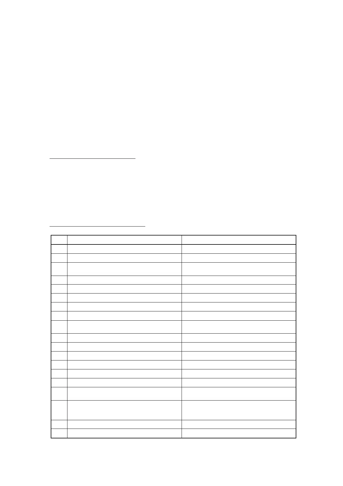
Signals between DCE and DTE
No. Command from DTE to DCE Information from DCE to DTE
1 Changing EGC channel Network information
2 Abort Current channel type
3 Alarm stop
Rx message data
(LES, date, priority, size, etc)
4 Finding TX message storage area EGC message
5 Login Login status
6 Logout TDM Information
7 Forced clear No. of RX message in DCE
8 Message transmission start BBER
9 Distress alert
Available memory size for RX message in
DCE
10 Start PV test start MES status
11 TX channel Current TDM type
12 Message delivery confirmation request NCS in use
13 Common channel assignment PV test result
14 NCS scan Message transmission result
15 Distress alert test Message delivery information
16 Response for repeating
Request for repeating (distress alarm, distress
alarm test)
17 Message transfer
DCE information
(Status, position, Self-monitoring,
self-test result)
18 Self-test start Alarm (Print, command response, etc.)
19 Polling data
 Loading...