6-7
Antenna Power Supply NG
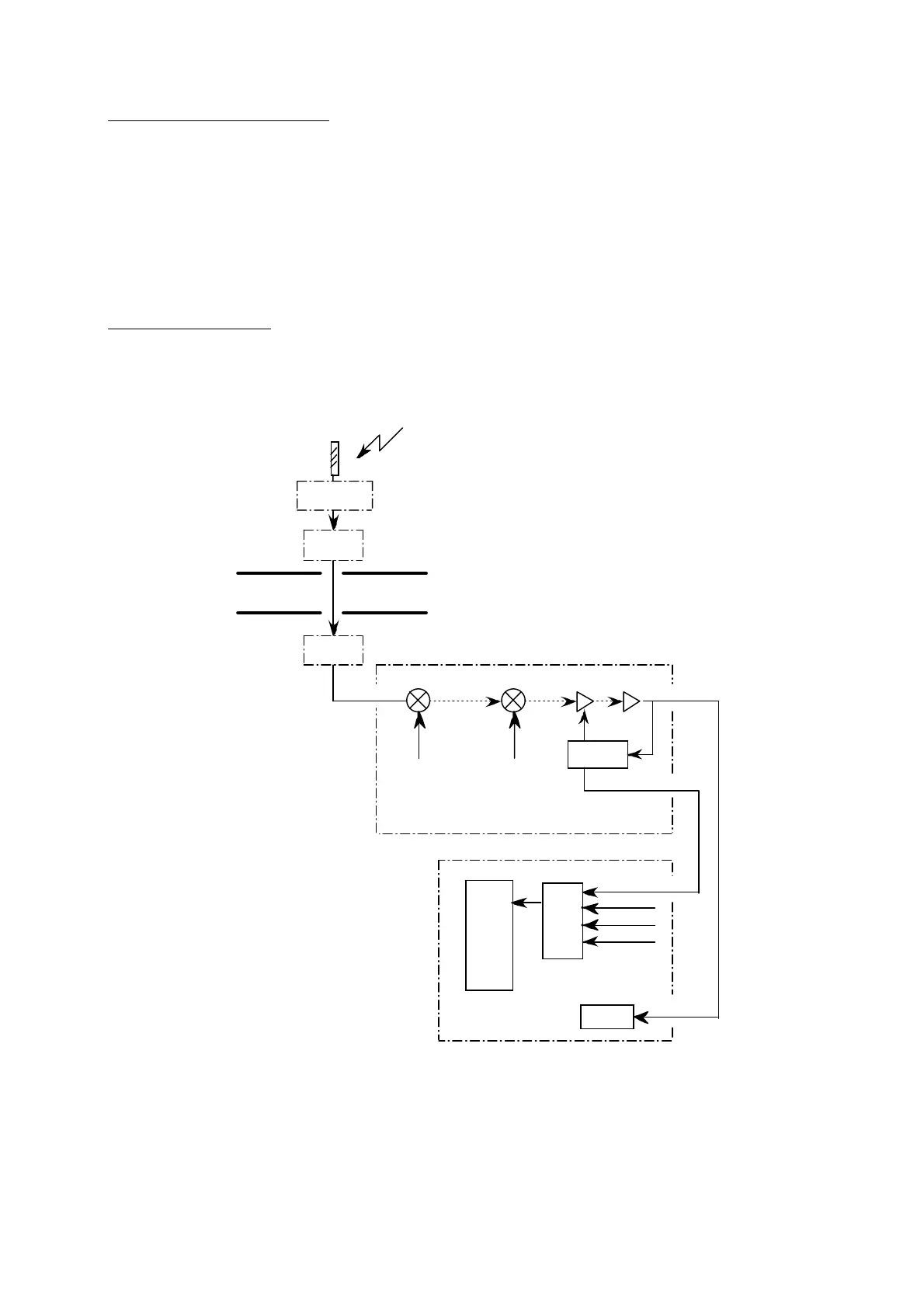
RX+18V/TX+29V, supply voltage to the antenna is divided by R61 and R62 to generate
a monitor signal ANT VOL. The A/D converter (U71) receives the ANT VOL signal and
sends it to the CPU2. If the voltage is not within the rating, “NG” will appear to indicate
short-circuit and/or disconnection. The voltage between J4, #6(+) and J4,#5(-) must be;
RX; 0.91 to 1.01 Vdc
TX; 1.45 to 1.49 Vdc
RX AGC Level NG
CPU 2 (U23) monitors the IF AGC level from the RF CON Board. If the level is less than
80, the receiver circuit in the antenna unit, TX Board, or RF CON Board may be
defective.
AGC AMP
CPU 2
(U23)
J6
CPU (16P0148)
TX
ANT
DIPLEXER
Antenna unit
Communication unit
U25
1530 - 1545MHz
1530 - 1545MHz
Q12
90.05MHz
50kHz
RX Lo
(1620.05-1635.05MHz)
2nd Lo
(90.1MHz)
U30,31
U33
50kHz
ANT CUR
ANT VOL
A/D
(U71)
AGC LEV
TX LEV
RF CON (16P0147)
AGC LEV
DEMOD
J2-17
J10-17
J2-4
J10-4
U32
 Loading...