6-9
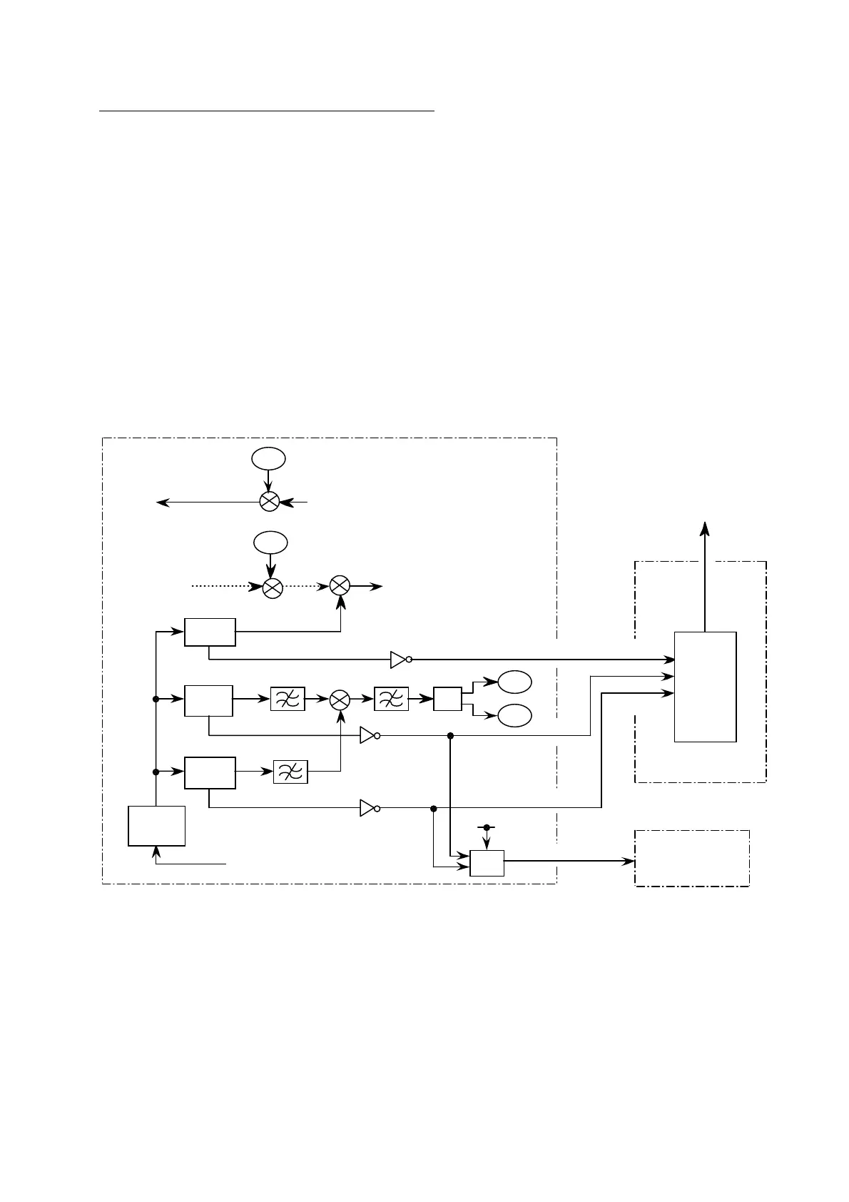
Synthe 1st-1Local, 2Local, RX 2nd Local NG
Synthe 1 st – 1 Local
When the PLL (U15) unlocks, LD(Lock Detect) line becomes to “L” level. The
CPU 2 receives the unlock signal and generates the NG indication.
Synthe 1 st – 2 Local
When the PLL (U10) unlocks, LD(Lock Detect) line becomes to “L” level. The
CPU 2 receives the unlock signal and generates the NG indication.
Synthe RX 2 nd Local
When the PLL (U34) unlocks, LD(Lock Detect) line becomes to “L” level. The
CPU 2 receives the unlock signal and generates the NG indication.
UNLOCK 1 and 2 signals are also used to generate 5V TX ON signal which controls the
TX circuit on the TX board. When the PLL, either of U10 or U15 unlocks, transmission
is automatically stopped.
PLL 3
LD
PLL 2
(MAIN)
LD
PLL 1
(SUB)
LD
U34
90.1MHz
90.05MHz
Q12
50kHz IF
UNLOCK 3
UNLOCK 1
UNLOCK 2
U10
U15
730MHz
900MHz
Q39
FL1
FL7 FL2
U5
U6
U6
DIV
RX Lo
TX Lo
VCXO
(15.6MHz)
VCXO CNT
Q25
1530-1545MHz
RX Lo
1620.05-1635.05MHz
TX Lo
1626.5-1646.5MHz
S-DATA
BPSK
1626.5-1646.5MHz
TX
CPU 2
(U23)
UNLOCK 3
UNLOCK 2
UNLOCK 1
J2-10
J2-12
J2-11
RF CON (16P0147)
CPU (16P0148)
J10-12/10/11
5V TX
J7-2
TX (16P0157)
5V TX ON
U7/8
To terminal unit
 Loading...