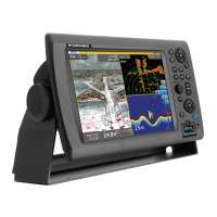
6.1.2. Basic Plotter/Radar/Fish Finder Installation
This is a single station Plotter/Radar/Fish Finder installation.
The Furuno GPS (FUSA P/N BBWGPS) is directly connected to 7-Pin Port DATA1 of
the MFD. Since two Ethernet sensors are on the network (DRS Radar and Fish Finder),
a network switch (FUSA P/N HUB101) is necessary. In this case the Radar power cable
is directly connected to the back of the MFD8/12 (DRSxD (Domes) can be powered
directly by any MFD. For DRSxA (Open) check compatibility). The Ethernet side of the
DRS Siamese cable may be extended using a coupler (FUSA P/N= RJ4-5CN-STR) and
an Ethernet cable.
Optional Ethernet Cables that can be used:
- 2 Meter RJ45 to RJ45 Ethernet Cable (P/N 000-167-175)
- 5 Meter RJ45 to RJ45 Ethernet Cable (P/N 000-167-176)
- 10 Meter RJ45 to RJ45 Ethernet Cable (P/N 000-167-177)
-Note that the HUB101 and all MFDs have “AUTO MDX” Ethernet Ports. This means
that they will automatically adjust for straight and cross-over Ethernet cables!
-Note that this installation will not allow Radar Overlay or ARPA target acquisition. If
these functions are desired, a Heading Compass sensor such as the Furuno
PG500/SC30/SC50 is required (see installation example on pg72)
 Loading...