C
ONNECTING THE
GY701
TO YOUR
R
ECEIVER
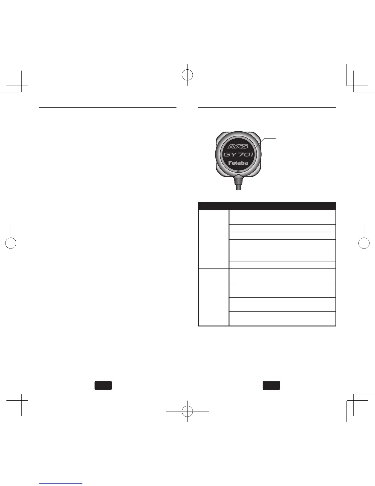
LED
I
NDICATOR
D
ESCRIPTION
Slow Flash: 1/2 Second or longer
Fast Flash: 1/4 Second or shorter
LED Indicator
CONDITION LED INDICATOR DESCRIPTION
Initialization Red Double Flash No Receiver Pulse or Sensor
Error
Slow Blue Flash Warm-Up
Fast Blue Flash Sensor Initialization
Slow Red Flash Governor Warning
Program-
ming
Blue Single Flash Parameter Programming
Mode
Slow Blue Flash Rudder Limit Setting Mode
Operating Solid Blue Normal Mode, Ready for
Flight
Solid Red AVCS Mode, Ready for
Flight
Slow Violet Flash Offset from the Neutral Posi-
tion (AVCS)
Fast Blue or Red
Flash
Gyro is Rotating
Connect the supplied extensions to the GY701
connecter. Route the wires through the helicopter
mechanics and connect them to the appropriate
receiver channels. To determine the appropriate
receiver channels please check your transmitter’s
instruction manual. Using wire mounts, wiring
xtures molded into the helicopter, or hook and
loop material, route the extensions to the receiver.
Ensure that the extensions leading to the receiver
cannot become entangled in rotating components
and make sure the extensions are not rubbing
against metal or carbon ber which may damage
the wires.
Once the power system is installed into your heli-
copter please move onto the later section to learn
how to program the gyro.