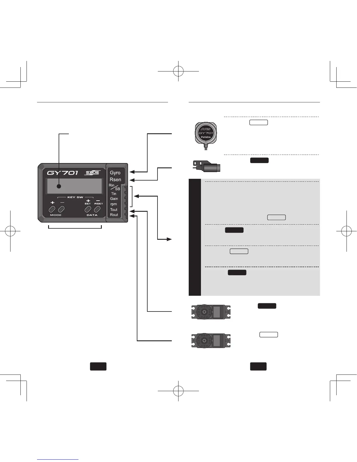
LCD Display
• Displays the set data and
operation status.
Edit Keys
• Used when setting data.
• Operated by pushing with the
accessory mini screwdriver.
• Connect the GY701 and the
receiver with the supplied ex-
tensions. [(3) to (6)]
When using an S.BUS re-
ceiver, (4) to (6) are not con-
nected.
• GY701 power requirement:
4.8V (from receiver)
(1) Gyro:
Gyro
• Connect the gyro sensor.
*Insert the sensor connector until it
is firmly locked.
(2) Rsen:
Governor
• Connect the speed sensor.
Receiver
(3) Rin/SB:
• S.BUS receiver: Connect to the S.BUS out-
put of the receiver.
• Other than S.BUS receiver: Connect to the
rudder channel output.
Gyro
(4) Tin:
Governor
• Connect to the throttle channel output.
(5) Gain:
Gyro
• Connect to the gyro gain channel output.
(6) rpm:
Governor
• Connect to the governor speed channel
output.
(7) Tout:
Governor
• Connect the throttle servo.
(8) Rout:
Gyro
• Connect the rudder servo.
(1)
(2)
(7)
(8)
(3)-(6)